


248 Fieldbus Communication
WAGO-I/O-SYSTEM 750
750-882 Media Redundancy ETHERNET Controller
Manual
1.5.0
12.2.5.1 Accessing Register Values
You can use any MODBUS application to access (read from or write to) register
values. Both commercial (e.g., “Modscan”) and free programs (from
http://www.modbus.org/tech.php
) are available.
The following sections describe how to access both the registers and their
values.
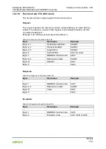
12.2.5.2 Watchdog Registers
The watchdog monitors the data transfer between the fieldbus master and the
coupler/controller. Every time the coupler/controller receives a specific request
(as define in the watchdog setup registers) from the master, the watchdog timer
in the coupler/controller resets.
In the case of fault free communication, the watchdog timer does not reach its
end value. After each successful data transfer, the timer is reset.
If the watchdog times out, a fieldbus failure has occurred. In this case, the
fieldbus coupler/controller answers all following MODBUS TCP/IP requests with
the exception code 0x0004 (Slave Device Failure).
In the coupler/controller special registers are used to setup the watchdog by the
master (Register addresses 0x1000 to 0x1008).
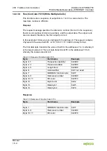
By default, the watchdog is not enabled when you turn the coupler/controller on.
To activate it, the first step is to set/verify the desired time-out value of the
Watchdog Time register (0x1000). Second, the function code mask must be
specified in the mask register (0x1001), which defines the function code(s) that
will reset the timer for the first time. Finally, the Watchdog-Trigger register
(0x1003) or the register 0x1007 must be changed to a non-zero value to start the
timer subsequently.
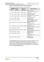
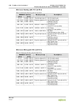
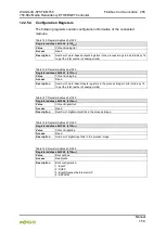
Table 129: MODBUS registers (Continuation)
Register
address
Acces
s
Length
(Word)
Description
0x2020
R
1 … 16
Short description controller
0x2021
R
1 … 8
Compile time of the firmware
0x2022
R
1 … 8
Compile date of the firmware
0x2023
R
1 … 32
Indication of the firmware loader
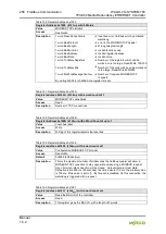
0x2030
R
1 … 65
Description of the connected I/O modules (module 0…64)
0x2031
R
1 … 64
Description of the connected I/O modules (module 65…128)
0x2032
R
1 … 64
Description of the connected I/O modules (module 129…192)
0x2033
R
1 … 63
Description of the connected I/O modules (module 193…255)
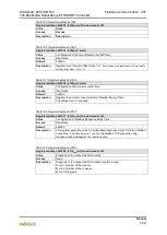
0x2040
W
1
Software reset (Write sequence 0x55AA or 0xAA55)
0x2041
W
1
Format flash disk
0x2042
W
1
Extract HTML sides from the firmware
0x2043
W
1
Factory settings