


14
Device Description
EPSITRON®
787-1675 Switched-Mode Power Supply with Integrated UPS Charger and Controller
Manual
Version 1.0.0
Pos: 18 /All e Seri en ( Allgemei ne Module)/Ü berschriften für alle Serien/Gerätebeschr eibung/Ansicht - Ü berschrift 2 @ 4\mod_1240984217343_21.doc @ 31958 @ 2 @ 1
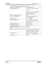
3.1
View
Pos: 19 /Serie 787 (EPSITRON)/Ger ätebeschrei bung/Ansi cht/Ansicht 787- 1675 @ 13\mod_1345791639239_21.doc @ 101944 @ @ 1
Figure 1: View of device
Table 3: Legend for "View" figure
No. Designation
Reference
1
CAGE CLAMP
®
connections
for 24 VDC output voltage
"Device description" >
"Connections" > "Load"
2
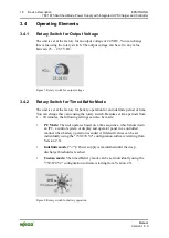
Rotary switch for setting the output
voltage
"Device Description" > "Operating
Elements" > "Rotary Switch for
Output Voltage"
3
CAGE CLAMP
®
connections
for 100 … 240 VAC input voltage
"Device Description" >
"Connections" > "Power Supply"
4
RS-232 serial interface
"Device Description" >
"Connections" > "RS-232
Interface"
5
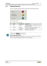
LEDs
"Device Description" > "Display
Elements"
6
Rotary switch for setting the timed
buffer mode
"Device Description" > "Operating
Elements" > "Rotary Switch for
Timed Buffer Mode"
7
CAGE CLAMP
®
connections for
battery, control and signaling contacts
"Device Description" > "Operating
Elements" > "Battery, Control and
Signaling Contacts"
Pos: 20 /D okumentation allgemei n/Glieder ungselemente/---Seitenwechsel--- @ 3\mod_1221108045078_0.doc @ 21810 @ @ 1