92
Fieldbus Communication
WAGO-I/O-SYSTEM 750
750-306 DeviceNet
TM
Fieldbus Coupler
Manual
Version 2.0.0
10.1.3.2 Data Exchange
Process data are exchanged between scanner and DeviceNet
TM
device by means
of the following three mechanisms:
•
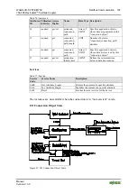
Polled I/O Connection
Slaves are polled cyclically by the master.
•
Change of Cyclic/State
Message are transmitted either cyclically by the master or the slave or in the
event of a state change.
•
Bit-Strobe
All slaves are polled by the master by means of a command.
10.1.4
Process Data and Diagnostic Status
The data are transmitted between master and slave in the form of objects,
distinguishing between input and output objects. The structure of the objects is
determined by assembly objects, which is used to group attributes of different
application objects. Input/output data from different objects can be combined into
data blocks and transmitted via a communication link.
10.1.4.1 Process Image
The process image is distinguished between input and output process image.
The assembly object provides a statically configured process image in instances 1
through 9.
By setting the “Produced Connection Path” and the “Consumed Connection Path”
for individual I/O connections (poll, bit strobe, change of state or change of
value), the required process image can be selected.
The structure of the individual instances of the assembly object is described
below.
10.1.4.1.1 Assembly Instances
Permanently pre-programmed (static) assemblies in the device permit easy and
rapid transmission of input and output images from the fieldbus coupler/controller
to the master. For this purpose, various assembly instances are provided in the
fieldbus coupler/controller:
•
Output 1 (“I/O Assembly Instance 1”)
The entire output data image is transmitted from the master to the fieldbus
coupler via the corresponding I/O message connection. The data length
corresponds to the quantity of output data in bytes. The analog output data
come before the digital output data.

