38
Device Description
WAGO-I/O-SYSTEM 750
750-306 DeviceNet
TM
Fieldbus Coupler
Manual
Version 2.0.0
4.1
View
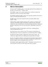
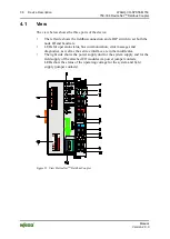
The view below shows the three parts of the device:
•
The left side shows the fieldbus connection and a DIP switch to set both the
node ID and baud rate.
•
LEDs for operation status, bus communication, error messages and
diagnostics, as well as the service interface are in the middle area.
•
The right side shows the power supply unit for the system supply and for the
field supply of the attached I/O modules via power jumper contacts.
LEDs show the status of the operating voltage for the system and field
supply (jumper contacts).
Figure 21: View DeviceNet
TM
Fieldbus Coupler

