WAGO-I/O-SYSTEM 750
Device Description
37
750-306 DeviceNet
TM
Fieldbus Coupler
Manual
Version 2.0.0
4
Device Description
The DeviceNet
TM
Fieldbus Coupler 750-306 links the WAGO-I/O-SYSTEM 750
as a slave to the DeviceNet
TM
fieldbus system.
This fieldbus coupler can be used for applications in mechanical and systems
engineering, as well as in the processing industry.
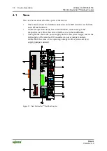
The fieldbus connection is made via 231 series 5-pin plug connector of the
WAGO
MULTI CONNECTION SYSTEM (MCS)
.
The DIP switch can be used to specify baud rate and station address of the
fieldbus coupler.
In the Fieldbus Coupler, all input signals from the sensors are combined. After
connecting the Fieldbus Coupler, the Fieldbus Coupler determines which I/O
modules are on the node and creates a local process image from these. Analog and
specialty module data is sent via words and/or bytes; digital data is grouped bit-
by-bit.
The local process image is divided into two data zones containing the data
received and the data to be sent.
The process data is sent via the DeviceNet
TM
fieldbus to a control system for
further processing. The process output data is sent via the DeviceNet
TM
fieldbus.
The data of the analog modules is mapped first into the process image. The
modules are mapped in the order of their physical position after the Coupler.
The bits of the digital modules are combined into bytes and then mapped after the
analog ones in the process image. If the number of digital I/Os is greater than 8
bits, the Fieldbus Coupler automatically begins a new byte.
The fieldbus coupler supports the DeviceNet
TM
“Bit Strobe” function where the
function is limited to the extent that only the status byte is supplied.

