WAGO-I/O-SYSTEM 750
I/O Modules 141
750-306 DeviceNet
TM
Fieldbus Coupler
Manual
Version 2.0.0
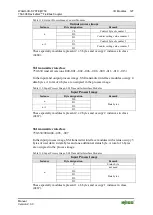
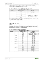
(Mode 2), the mailbox and the cyclical process data are mapped next. The
remaining bytes contain the remaining process data.
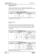
Table 142: Input/Output Process Image, WAGO AS-Interface Master Module
Input/Output Process Image
Instance
Byte designation
Remark
n
C0/S0
Control/status byte
-
not used
D0
Mailbox (0, 6, 12 or 18 bytes) and
process data (0 ... 32 bytes)
D1
D2
…
D46
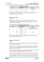
These specialty modules represent 1 x 12...48 bytes and occupy 1 instance in class
(0x67) and 1 instance in class (0x68).
4-channel IO-Link master
750-657
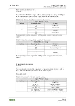
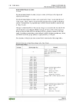
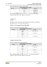
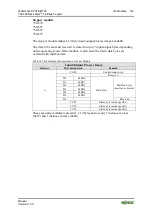
The length of the process image of the 4-channel IO-Link Master can be adjusted
to a fixed size of 4, 6, 8, 10, 12, 16, 20 or 24 bytes.
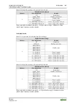
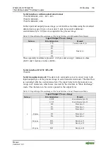
Table 143: Input/Output Process Image, I/O-Link Master
Input/Output Process Image
Instance
Byte designation
Remark
n
4 bytes
S0/C0
Control/status byte
FC0
Acyclic channel
Register byte 0
MB0
Mailbox byte
Register byte 1
SIO
SIO Byte
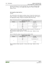
6 bytes
D0
Data byte 0
D1
Data byte 1
8 bytes
D2
Data byte 2
D3
Data byte 3
10 bytes
D4
Data byte 4
D5
Data byte 5
12 bytes
D6
Data byte 6
D7
Data byte 7
16 bytes
D8
Data byte 8
D9
Data byte 9
D10
Data byte 10
D11
Data byte 11
20 bytes
D12
Data byte 12
D13
Data byte 13
D14
Data byte 14
D15
Data byte 15

