134 I/O Modules
WAGO-I/O-SYSTEM 750
750-306 DeviceNet
TM
Fieldbus Coupler
Manual
Version 2.0.0
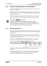
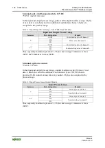
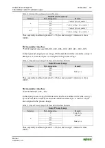
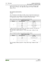
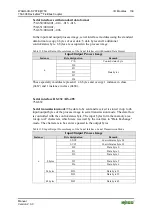
Table 133: Output Process Image, Radio Receiver I/O Module
Output process image
Instance
Byte designation
Remark
n
C
Control byte
-
not used
n+1
-
-
These specialty modules represent 2 x 2 bytes and occupy 2 instances in class
(0x67) and 2 instances in class (0x68).
MP Bus Master Module
750-643
In the input and output process image, the MP bus master module occupies 8
bytes of user data: 6 data bytes and 2 additional control/status bytes. 8 bytes are
occupied in the process image.
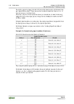
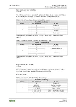
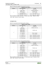
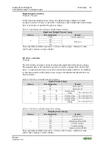
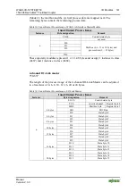
Table 134: Input/Output Process Image, MP Bus Master Module
Input/Output Process Image
Instance
Byte designation
Remark
n
C0/S0
Control/status byte
C1/S1
Additional control/status byte
D0
Data bytes
D1
D2
D3
D4
D5
These specialty modules represent 1 x 8 bytes and occupy 1 instance in class
(0x67) and 1 instance in class (0x68).
Bluetooth
®
RF transceiver
750-644
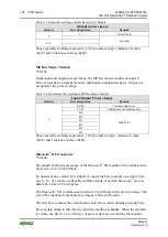
The length of the process image of the
Bluetooth
®
I/O module can be adjusted to a
fixed size of 12, 24 or 48 Byte.
It consists of one control byte (input) or one status byte (output), one empty byte,
one 6-, 12- or 18-byte overlayable mailbox (mode 2) and the
Bluetooth
®
process
data with a size of 4 to 46 bytes.
The
Bluetooth
®
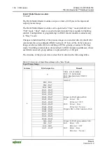
I/O module uses between 12 to 48 bytes in the process image. The
size of the input and output process images is always the same.
The first byte contains the control/status byte; the second contains an empty byte.
Process data attach to this directly when the mailbox is hidden. When the mailbox
is visible, the first 6, 12 or 18 bytes of process data are overlaid by the mailbox

