Manual
WAGO-I/O-SYSTEM 750
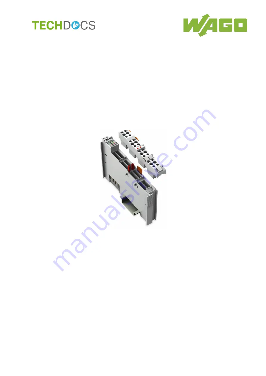
753-649
M-Bus Master Module
for the Connection of M-Bus Devices
Version 1.1.2
Page 1: ...Manual WAGO I O SYSTEM 750 753 649 M Bus Master Module for the Connection of M Bus Devices Version 1 1 2...
Page 2: ...E Mail support wago com Every conceivable measure has been taken to ensure the accuracy and completeness of this documentation However as errors can never be fully excluded we always appreciate any i...
Page 3: ...al Bus 17 3 2 2 Power Jumper Contacts Field Supply 18 3 2 3 CAGE CLAMP Connectors 19 3 3 Display Elements 20 3 4 Operating Elements 21 3 5 Schematic Diagram 21 3 6 Overcurrent Shutdown 22 3 7 Technica...
Page 4: ...ation 38 7 2 Configuration and Data Access 39 7 2 1 Configuration and Access via WAGO I O PRO 39 7 2 2 Configuration and Access via MBSheet and MBCONF 40 7 2 2 1 Install Components 41 7 2 2 2 Open MBS...
Page 5: ...l and in the manual for the used fieldbus coupler or controller Consider power layout of the WAGO I O SYSTEM 750 In addition to these operating instructions you will also need the manual for the used...
Page 6: ...a moderate risk potentially hazardous situation which if not avoided could result in death or serious injury Personal Injury Indicates a low risk potentially hazardous situation which if not avoided m...
Page 7: ...EM 750 Notes about this Documentation 7 753 649 M Bus Master Module Manual Version 1 1 2 Additional Information Refers to additional information which is not an integral part of this documentation e g...
Page 8: ...es are marked in italic type e g C Program Files WAGO Software Menu Menu items are marked in bold letters e g Save A greater than sign between two names means the selection of a menu item from a menu...
Page 9: ...All changes to the coupler or controller should always be carried out by qualified personnel with sufficient skills in PLC programming 2 1 3 Use of the 750 Series in Compliance with Underlying Provisi...
Page 10: ...dules can be controlled by the safety function 2 1 4 Technical Condition of Specified Devices The devices to be supplied ex works are equipped with hardware and software configurations which meet the...
Page 11: ...nst contact Prevent fire from spreading outside of the enclosure Offer adequate protection against UV irradiation Guarantee mechanical stability Restrict access to authorized personnel and may only be...
Page 12: ...and insulating properties such as aerosols silicones and triglycerides found in some hand creams If you cannot exclude that such materials will appear in the component environment then install the co...
Page 13: ...vices are equipped with electronic components that may be destroyed by electrostatic discharge when touched Please observe the safety precautions against electrostatic discharge per DIN EN 61340 5 1 3...
Page 14: ...k and the processing software When queried the M Bus master transmits control commands to actuators via the two wire cable or reads data from consumption meters and sensors The data recorded is passed...
Page 15: ...tem Fieldbus Coupler Controller Item Number Firmware Revision Status Ethernet Controller 750 852 09 750 880 09 750 881 09 750 882 09 750 885 09 BA application controller 750 884 07 PFC100 fieldbus con...
Page 16: ...Status LEDs Device Description Display Elements 3 Data contacts Device Description Connectors 4 CAGE CLAMP connectors Device Description Connectors 5 Pull tab Mounting I O Modules with Pluggable Wirin...
Page 17: ...vailable as self cleaning gold spring contacts Figure 2 Data Contacts Do not place the I O modules on the gold spring contacts Do not place the I O modules on the gold spring contacts in order to avoi...
Page 18: ...Jumper Contacts Table 5 Legend for Figure Power Jumper Contacts Contact Type Function 1 Spring contact Potential transmission Uv for field supply 2 Spring contact Potential transmission 0 V for field...
Page 19: ...ors Figure 4 CAGE CLAMP Connections The CAGE CLAMP outputs are short circuit protected Table 6 Legend for Figure CAGE CLAMP Connections Connection Function M Bus Connection for M Bus cable positive M...
Page 20: ...rent Off No error Red Overcurrent on M Bus cables D Not used E Power supply status Off No field side power supply M Bus master fault Green steady M Bus ready Green flashing Value of the external power...
Page 21: ...ule Manual Version 1 1 2 3 4 Operating Elements The I O module 753 649 does not have any electro mechanical operating elements Changes to the configuration and parameters are made via the higher order...
Page 22: ...wn is signaled via an LED see section Device Description Display Elements After the minimum shutdown time passes the M Bus master attempts to turn the M Bus power back on If the M Bus current threshol...
Page 23: ...2 5 5 Voltage via power jumper contacts 23 4 V 25 2 VDC Currentmax via power jumper contacts 10 A Recommended power supplies EPSITRON CLASSIC family 1st generation 787 612 2nd generation 787 1606 EPS...
Page 24: ...aud M Bus standard loadmax 40 pcs 1 5 mA each Overcurrent shutdown Type of monitoring Active current monitoring Threshold Approx 120 mA fixed setting Minimum shutdown time 500 ms With a conductor size...
Page 25: ...2000 m Surrounding air temperature storage 20 C 85 C Storage altitude above sea level 3000 m Relative humidity without condensation 10 95 Degree of protection IP20 Exposure to pollutants Per IEC 6006...
Page 26: ...nformation about approvals Detailed references to the approvals are listed in the document Overview Approvals WAGO I O SYSTEM 750 which you can find via the internet under www wago com DOWNLOADS Docum...
Page 27: ...Immunity to interference EN 61000 6 2 EMC CE Emission of interference EN 61000 6 3 Note Use recommended power supplies for reliable CE immunity to interference and emission of interference compliance...
Page 28: ...design of the node in terms of the potential groups connection via the power contacts are recognized as the I O modules with power contacts blade contacts cannot be linked to I O modules with fewer po...
Page 29: ...O module so that the tongue and groove joints to the fieldbus coupler or controller or to the previous or possibly subsequent I O module are engaged Figure 7 Insert I O Module Example 2 Press the I O...
Page 30: ...re 9 Removing the I O Module Example Electrical connections for data or power jumper contacts are disconnected when removing the I O module 5 3 I O Modules with Pluggable Wiring Level Series 753 For w...
Page 31: ...ure 12 Attachment of Cable Binders 5 3 1 Coding Coding using small plastic pins and sockets facilitates mating of the I O module with the appropriate plug 1 Insert the pin into the socket Figure 13 As...
Page 32: ...Inserting the Coding Fingers 3 Place the plug onto the I O module Figure 15 Plugging the Plug into Place 4 When the plug is removed the sockets remain in the I O module The coded plug can only fit in...
Page 33: ...ing the orange pull tab on the plug toward the top of the I O module Figure 17 Pulling the Pull Tab The plug detaches from the I O module Figure 18 Removing the Plug Without Tools 2 Alternatively you...
Page 34: ...GE CLAMP Do not connect more than one conductor at one single connection If more than one conductor must be routed to one connection these must be connected in an up circuit wiring assembly for exampl...
Page 35: ...WAGO I O SYSTEM 750 Connect Devices 35 753 649 M Bus Master Module Manual Version 1 1 2 6 2 Connection Example Figure 21 Connection Example...
Page 36: ...VDC 25 2 VDC When continuously illuminated LED E indicates that the supply voltage is in the permissible range When LED E blinks the supply voltage is outside the permissible range see section Device...
Page 37: ...master and slave is the lower the baud rate is The supported combinations are given in the section Technical Data Communication Excessive cable lengths can trigger the overcurrent shutdown see section...
Page 38: ...necting the serial service port of the fieldbus controller to the 750 921 WAGO Bluetooth Adapter available as an accessory In the example given here the fieldbus node consists of the following WAGO I...
Page 39: ...e If needed each module can be given the desired address of the M Bus slave If a function block sends a query to the corresponding meter the meter supplies the queried data such as the manufacturer ID...
Page 40: ...provided by Relay Reinecke Elektronikentwicklung und Layout GmbH from the Relay website at www relay de The installation package of the M Bus Connector software already contains a version of MBSheet...
Page 41: ...e driver Click Install Figure 22 Windows Security Alert about the Eltima Software Before the installation of M Bus Connector is completed you receive a Windows alert containing the option Start MBShee...
Page 42: ...ioning WAGO I O SYSTEM 750 753 649 M Bus Master Module Manual Version 1 1 2 Figure 23 Windows Prompt about Installation of the MBSheet Software Once all applications are installed you can use MBSheet...
Page 43: ...or Control mode is activated in WAGO I O CHECK deactivate it Click the corresponding button in the toolbar so that it is no longer highlighted This step is unnecessary if configuring for the first ti...
Page 44: ...AGO I O SYSTEM 750 753 649 M Bus Master Module Manual Version 1 1 2 The MBSheet user interface then opens Figure 25 Graphical User Interface of MBSheet While MBSheet is open the WAGO I O CHECK user in...
Page 45: ...required to be installed Proceed as follows in order to access MBCONF 1 Open MBSheet see section Start Up Open MBSheet 2 Open MBCONF 7 2 2 4 Use MBSheet and MBCONF Download manuals for MBSheet and MB...
Page 46: ...roceed as follows 1 Switch to the application indicated and close it 2 Close the notification window The virtual COM Port is then deleted from the system configuration and the WAGO I O CHECK user inte...
Page 47: ...Module to Plug Using Mini WSB Tags 31 Figure 12 Attachment of Cable Binders 31 Figure 13 Assembling the Coding Fingers 31 Figure 14 Inserting the Coding Fingers 32 Figure 15 Plugging the Plug into Pla...
Page 48: ...r Contacts 18 Table 6 Legend for Figure CAGE CLAMP Connections 19 Table 7 Legend for the Figure Display Elements 20 Table 8 Technical Data Device 23 Table 9 Technical Data Power Supply 23 Table 10 Tec...
Page 49: ...WAGO I O SYSTEM 750 List of Tables 49 753 649 M Bus Master Module Manual Version 1 1 2...
Page 50: ...WAGO Kontakttechnik GmbH Co KG Postfach 2880 D 32385 Minden Hansastra e 27 D 32423 Minden Phone 49 571 887 0 Fax 49 571 887 844169 E Mail info wago com Internet www wago com...