64 Commissioning
WAGO-I/O-SYSTEM 750 XTR
750-652/040-000 Serial Interface RS-232/RS-485 XTR
Manual
Version 1.3.0
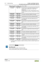
Table 45: Transmission of a Block of More Than 512 Bytes
*)
Control byte 0
Control byte 1
'0110.1001'
'0XXX. X101'
Controller fills the output buffer with 46 bytes and set
bit 3 (SC) of the control byte 0 for the start of the
transmission.
Bit 3 (SC) of the control byte 0 must always be set if the
controller transmits more than 512 bytes of data to the I/O
module.
Status byte 0
Status byte 1
'0XXX.X0X1'
'0000. 1XXX'
I/O module confirms the acceptance of the data.
Control byte 0
Control byte 1
'0110.1000'
'0XXX. X101'
Controller takes bit 0 (TR) of the control byte 0 back.
Status byte 0
Status byte 1
'0XXX.X0X0'
'0XXX. 0XXX'
I/O module begins with the data transmission via the
serial interface.
Control byte 0
Control byte 1
'0110.1001'
'0XXX. X101'
Controller fills the output buffer with another 46 bytes of
data.
Status byte 0
Status byte 1
'0XXX.X0X1'
'0000. 0XXX'
I/O module confirms the acceptance of the data.
Status byte 0
Status byte 1
'0XXX.X0X1'
'0000. 1XXX'
All data saved in the output buffer is transmitted via the
serial interface.
Control byte 0
Control byte 1
'0110.1001'
'0XXX. X101'
Controller fills the output buffer with another 46 bytes of
data.
Status byte 0
Status byte 1
'0XXX.X0X1'
'0000. 0XXX'
I/O module confirms the acceptance of the data.
Status byte 0
Status byte 1
'0XXX.X0X0'
'0XXX. 0XXX'
I/O module continues the data transmission via the serial
interface.
Status byte 0
Status byte 1
'0XXX.X0X1'
'0000. 1XXX'
All data saved in the output buffer is transmitted via the
serial interface.
Control byte 0
Control byte 1
'0XXX.0XX0'
'0XXX. 1XXX'
Controller takes bit 3 (SC) of the control byte 0 back.
*)
The table shows the transmission method from the time at which more than 500 bytes is in the
output buffer.
Illustration note
An X is used if the value is not relevant here.
An XX means that the entire value is not relevant.


