


44 Function Description
WAGO I/O System 750
750-637 Incremental Encoder Interfaces
Manual
Version 1.6.1
Public
5
Function Description
</dg_
As a rule, incremental encoders supply two output signals from the encoder
tracks, offset by 90°. These signals are designated A and B. The difference
between the input signals is evaluated in the incremental encoder I/O module.
In addition to the two track signals, incremental encoders normally also have an
index track. This track contains only one impulse per rotation of the encoder.
From this impulse and the counter value, the absolute position of the encoder
can be determined within a revolution. As the index impulse is equal to the length
of a line of the track signals, the latch process should always be carried out with
the same direction of rotation.
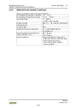
Table 36: Function Description – Inputs
Input
Description
I/O Module
Function
A, /A,
B, /B
Quadrature inputs,
RS-422
750-637
Track signal A or B of the
incremental encoder
750-637/000-003
Quadrature inputs,
24 V, differential
750-637/000-001
A,B
Quadrature inputs,
24 V, single-ended
750-637/000-004
750-637/000-002
C, /C
Initial point input,
RS-422
750-637
Track signal for the index
channel of the incremental
encoder.
Based on the operating
mode, the content of the
counter is placed in the
Latch register, or the set
value also loaded to the
counter on a positive edge
at this input.
750-637/000-003
Initial point input,
24 V, differential
750-637/000-001
C
Initial point input,
single-ended
750-637/000-002
750-637/000-004
LATCH
LATCH input,
24 V
750-637
Based on the operating
mode, the content of the
counter is placed in the
Latch register, or the set
value also loaded to the
counter on a positive edge
at this input.
750-637/000-001
750-637/000-002
750-637/000-003
750-637/000-004


