Manual
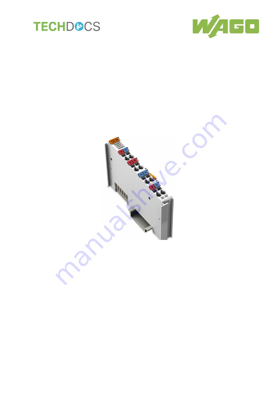
WAGO-I/O-SYSTEM 750
750-626/020-002
Power Supply Filter 24 VDC HI GF
Power Supply Filter (Surge); 24 VDC;
Higher Isolation; Ground Fault Diagnostics
Version 1.0.0
Page 1: ...Manual WAGO I O SYSTEM 750 750 626 020 002 Power Supply Filter 24 VDC HI GF Power Supply Filter Surge 24 VDC Higher Isolation Ground Fault Diagnostics Version 1 0 0...
Page 2: ...87 84 45 55 E Mail support wago com Every conceivable measure has been taken to ensure the accuracy and completeness of this documentation However as errors can never be fully excluded we always appre...
Page 3: ...ety Advice Precautions 12 3 Device Description 15 3 1 View 17 3 2 Connectors 18 3 2 1 Data Contacts Local Bus 18 3 2 2 Power Jumper Contacts Field Supply 19 3 2 3 CAGE CLAMP Connectors 20 3 3 Display...
Page 4: ...rine Applications in Ex i 42 7 Use in Hazardous Environments 45 7 1 Marking Configuration Examples 46 7 1 1 Marking for Europe According to ATEX and IECEx 46 7 1 2 Marking for the United States of Ame...
Page 5: ...nstructions in this manual and in the manual for the used fieldbus coupler or controller Consider power layout of the WAGO I O SYSTEM 750 In addition to these operating instructions you will also need...
Page 6: ...Indicates a moderate risk potentially hazardous situation which if not avoided could result in death or serious injury Personal Injury Indicates a low risk potentially hazardous situation which if not...
Page 7: ...s about this Documentation 7 750 626 020 002 Power Supply Filter 24 VDC HI GF Manual Version 1 0 0 Additional Information Refers to additional information which is not an integral part of this documen...
Page 8: ...nd data files are marked in italic type e g C Program Files WAGO Software Menu Menu items are marked in bold letters e g Save A greater than sign between two names means the selection of a menu item f...
Page 9: ...ironments All changes to the coupler or controller should always be carried out by qualified personnel with sufficient skills in PLC programming 2 1 3 Use of the 750 Series in Compliance with Underlyi...
Page 10: ...requirements These modules contain no parts that can be serviced or repaired by the user The following actions will result in the exclusion of liability on the part of WAGO Kontakttechnik GmbH Co KG...
Page 11: ...onic equipment sent to your local collection point Improper disposal of electrical and electronic equipment can be harmful to the environment and human health 2 1 5 2 Packaging Packaging contains mate...
Page 12: ...eded Offer adequate protection against contact Prevent fire from spreading outside of the enclosure Guarantee mechanical stability Restrict access to authorized personnel and may only be opened with t...
Page 13: ...urrent values When configuring the system do not exceed the permissible maximum current value If there is a higher power requirement you must use an additional supply module to provide the field volta...
Page 14: ...ove mentioned materials Clean tools and materials are imperative for handling devices modules Clean only with permitted materials Clean housing and soiled contacts with propanol Do not use any contact...
Page 15: ...everal of these feed segments which are supplied galvanically isolated from each other this module can locate the feed segment affected by the ground fault or limit the location of the ground fault Us...
Page 16: ...002 can be operated on the listed fieldbus couplers and controllers of the 750 series from the specified version Table 3 Compatibility List 750 626 020 002 Bus System Fieldbus Coupler Controller Item...
Page 17: ...d for Figure View Pos Description Details See Section 1 Marking possibility with Mini WSB 2 Status LEDs Device Description Display Elements 3 Data contacts Device Description Connectors 4 CAGE CLAMP c...
Page 18: ...evices are equipped with electronic components that may be destroyed by electrostatic discharge When handling the devices please ensure that environmental factors personnel work space and packaging ar...
Page 19: ...contact Potential feed in 0V Field for field supply Do not exceed maximum values via power contacts The maximum current that can flow through the power jumper contacts is 10 A The power jumper contac...
Page 20: ...AGE CLAMP Connectors Designation Connector Function 24V System OUT 1 Output system supply 24 VDC filtered 0V System OUT 5 Output system supply 0 VDC filtered 24V Field IN 2 Input field supply 24 VDC 6...
Page 21: ...tate Function A Status 24V System Off No 24 VDC operating voltage for system supply Green 24 VDC operating voltage for system supply C Status 24V Field Off No 24 VDC voltage supply via power jumper co...
Page 22: ...22 Device Description WAGO I O SYSTEM 750 750 626 020 002 Power Supply Filter 24 VDC HI GF Manual Version 1 0 0 3 5 Schematic Diagram Figure 6 Schematic diagram...
Page 23: ...ground diagnostics activated Supply voltage field 24 VDC SELV 25 30 power supply via CAGE CLAMP connection transmission via spring contact Current consumption field Typ 16 mA when a ground fault is d...
Page 24: ...ocal bus 8 bit input 8 bit output 3 6 5 Connection Type Table 10 Technical Data Field Wiring Wire connection CAGE CLAMP Cross section 0 08 mm 2 5 mm AWG 28 14 Stripped lengths 8 mm 9 mm 0 33 in Table...
Page 25: ...age category II Protection type IP20 Exposure to pollutants Per IEC 60068 2 42 and IEC 60068 2 43 Max contaminant concentration at relative humidity 75 SO2 25 ppm H2S 10 ppm Special conditions The com...
Page 26: ...ia the internet under www wago com DOWNLOADS Documentation System Description The following approval has been granted to 750 626 020 002 I O modules Conformity Marking The following approval is pendin...
Page 27: ...ules meet the following requirements on emission and immunity of interference EU EMC Directive 2014 30 EU EMC CE Emission of interference EN 61000 6 3 EMC CE Immunity to interference EN 61000 6 2 EMC...
Page 28: ...ith power contacts blade contacts cannot be linked to I O modules with fewer power contacts Risk of injury due to sharp edged blade contacts The blade contacts are sharp edged Handle the I O module ca...
Page 29: ...tion the I O module so that the tongue and groove joints to the fieldbus coupler or controller or to the previous or possibly subsequent I O module are engaged Figure 7 Insert I O Module Example 2 Pre...
Page 30: ...DC HI GF Manual Version 1 0 0 4 2 2 Removing the I O Module 1 Remove the I O module from the assembly by pulling the release tab Figure 9 Removing the I O Module Example Electrical connections for dat...
Page 31: ...to each CAGE CLAMP Do not connect more than one conductor at one single connection If more than one conductor must be routed to one connection these must be connected in an up circuit wiring assembly...
Page 32: ...ground fault diagnostics at the same time Enabling ground fault diagnostics at the same time influences the thresholds due to the parallel internal resistances of the modules Do not enable ground fau...
Page 33: ...ted in parallel because the internal resistance in the relevant supply network or feed segment changes due to the internal resistance of the test circuit The influence is greater the more filter modul...
Page 34: ...ss image The diagnostic messages may change during the test period VAL 1 in the input process image signals a valid ground fault test 6 1 Process Image Table 15 Input Process Image Bit 7 Bit 6 Bit 5 B...
Page 35: ...round fault diagnostics disabled The internal test circuit is separated from ground potential with high resistance 1 Ground fault diagnostics enabled Measuring circuit for ground fault diagnostics is...
Page 36: ...Window The Field Voltage field indicates whether the field voltage is present Field voltage available Requirement for ground fault diagnostics Field supply not available Check the field supply 4 Star...
Page 37: ...diagnostics is indicated as follows In WAGO I O CHECK By the Diagnostics enabled message in the dialog In the input process image Bit VAL 1 The measuring circuit is switched on and the transient phase...
Page 38: ...K Ground Fault Diagnostics Dialog Main Alarm 0V Disable If ground fault diagnostics is disabled the internal test circuit is separated from the ground potential with high resistance 1 Disable ground f...
Page 39: ...of the individual I O modules and in the 750 and 753 Series system manual Marine applications Class A All areas except bridge and open deck Class B All areas including bridge and open deck Applicatio...
Page 40: ...ower jumper contacts or have only single power jumper contacts depending on the I O function As a result transferring the corresponding potential is interrupted If downstream I O modules require a pow...
Page 41: ...use 750 601 or Supply module 24 VDC with fuse and diagnostics 750 610 4 Filter module 24 VDC HI GF 750 624 020 002 or Filter module 24 VDC HI 750 624 020 000 5 Supply module 230 VAC DC with diagnostic...
Page 42: ...shown with 750 624 xxx xxx for Field 2 Table 23 Legend for figure Power Supply Concept for Marine Applications in Ex i Class A shown with 750 624 xxx xxx for Field 2 No Explanation 1 Fieldbus Couplers...
Page 43: ...y Concept for Marine Applications in Ex i Class B shown with 750 626 xxx xxx for Field 2 Table 25 Legend for figure Power Supply Concept for Marine Applications in Ex i Class B shown with 750 626 xxx...
Page 44: ...GF Manual Version 1 0 0 Table 26 Explanation of the Legend for figure Power Supply Concept for Marine Applications in Ex i Class B shown with 750 626 xxx xxx for Field 2 Explanation HI High Isolation...
Page 45: ...hazardous areas and shall be used in accordance with the marking and installation regulations The following sections include both the general identification of components devices and the installation...
Page 46: ...002 Power Supply Filter 24 VDC HI GF Manual Version 1 0 0 7 1 Marking Configuration Examples 7 1 1 Marking for Europe According to ATEX and IECEx Figure 22 Marking Example According to ATEX and IECEx...
Page 47: ...Explosion group of dust T135 C Max surface temperature of the enclosure without a dust layer Dc Equipment protection level EPL Mining I Equipment group Mining M2 Category High level of protection Ex...
Page 48: ...50 750 626 020 002 Power Supply Filter 24 VDC HI GF Manual Version 1 0 0 Figure 24 Marking Example for Approved Ex i I O Module According to ATEX and IECEx Figure 25 Text Detail Marking Example for Ap...
Page 49: ...dust layer Dc Equipment protection level EPL Mining I Equipment Group Mining M2 M1 Category High level of protection with electrical circuits which present a very high level of protection Ex Explosion...
Page 50: ...tates of America NEC and Canada CEC Figure 26 Marking Example According to NEC Figure 27 Text Detail Marking Example According to NEC 500 Table 29 Description of Marking Example According to NEC 500 M...
Page 51: ...nt protection level EPL Associated apparatus with intrinsic safety circuits for use in Zone 20 IIC Group T4 Temperature class Gc Equipment protection level EPL Figure 29 Text Detail Marking Example fo...
Page 52: ...ark nA Type of protection ia IIIC Type of protection and equipment protection level EPL Associated apparatus with intrinsic safety circuits for use in Zone 20 IIC Group T4 Temperature class Gc Equipme...
Page 53: ...ing when replacing components The product is an open system As such the product must only be installed in appropriate enclosures or electrical operation rooms to which the following applies Can only b...
Page 54: ...n particular Operating DIP switches coding switches or potentiometers Replacing fuses Wiring connecting or disconnecting of non intrinsically safe circuits is only permitted in the following cases The...
Page 55: ...elephone networks or telecommunication cables WARNING The radio receiver module 750 642 may only be used to connect to external antenna 758 910 WARNING Product components with fuses must not be fitted...
Page 56: ...ure 18 WAGO I O CHECK Disabling Ground Fault Diagnostics Dialog 38 Figure 19 Power Supply Concept for Marine Applications Class A and B shown with 750 624 xxx xxx for Field 2 40 Figure 20 Power Supply...
Page 57: ...Class A and B shown with 750 624 xxx xxx for Field 2 41 Table 22 Explanation of the Legend for Figure Power Supply Concept for Marine Applications Class A and B shown with 750 624 xxx xxx for Field 2...
Page 58: ...58 List of Tables WAGO I O SYSTEM 750 750 626 020 002 Power Supply Filter 24 VDC HI GF Manual Version 1 0 0...
Page 59: ...WAGO I O SYSTEM 750 59 750 626 020 002 Power Supply Filter 24 VDC HI GF Manual Version 1 0 0...
Page 60: ...WAGO Kontakttechnik GmbH Co KG Postfach 2880 D 32385 Minden Hansastra e 27 D 32423 Minden Phone 49 571 887 0 Fax 49 571 887 844169 E Mail info wago com Internet www wago com...