


WAGO-I/O-System 750
Diagnostics 121
750-370 PROFINET IO Fieldbus Coupler
Manual
Version 2.0.0
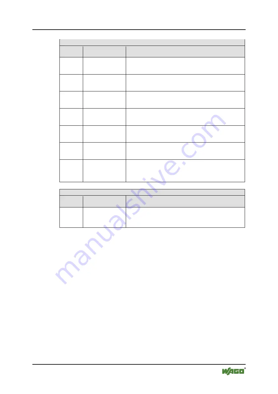
Table 55: Blink Code Table for the 'I/O' LED Signaling, Error Code 1
Error code 1: “Hardware and configuration error”
Error
Argument
Error Description Solution
8
Timeout during
serial EEPROM
access.
1. Turn off the power supply for the node.
2. Replace the fieldbus coupler.
3. Turn the power supply on again.
9
Fieldbus coupler
initialization error
1. Turn off the power supply for the node.
2. Replace the fieldbus coupler.
3. Turn the power supply on again.
10
Buffer voltage
failure Real Time
Clock (RTC)
1. Set the clock.
2. Get the power supply for the fieldbus coupler for at least
15 minutes to charge the Goldcap.
11
Fault when read
access to the Real
Time Clock (RTC)
1. Set the clock.
2. Get the power supply for the fieldbus coupler for at least
15 minutes to charge the Goldcap.
12
Fault when write
access to the Real
Time Clock (RTC)
1. Set the clock.
2. Get the power supply for the fieldbus coupler for at least
15 minutes to charge the Goldcap.
13
Error clocks interrupt
1. Set the clock.
2. Get the power supply for the fieldbus coupler for at least
15 minutes to charge the Goldcap.
14
Maximum number of
gateway or mailbox
modules exceeded
1. Turn off the power for the node.
2. Reduce the number of corresponding modules to a valid
number.
3. Turn the power on again.
Pos: 75.12 /Serie 750 ( WAGO-I/O-SYST EM)/Diagnose/F eldbuskoppler/-controll er/Bli nkcode-Tabellen - F ehl ercode 2...5 (750- 0333) @ 11\mod_1317133888384_21.docx @ 79834 @ @ 1
Table 56: Blink Code Table for the I/O LED Signaling, Error Code 2
Error code 2: -not used-
Error
Argument
Error Description Solution
-
Not used
-