


120 Diagnostics
WAGO-I/O-System 750
750-370 PROFINET IO Fieldbus Coupler
Manual
Version 2.0.0
•
After the second pause, the third flash sequence starts (approx. 1 Hz):
The I/O LED flashes twelve times.
Error argument 12 means that the internal data bus is interrupted behind the
twelfth active I/O module.
The thirteenth I/O module is either defective or has been removed from the
network.
Pos: 75.11 /Serie 750 ( WAGO-I/O-SYST EM)/Diagnose/F eldbuskoppler/-controll er/Bli nkcode-Tabellen - F ehl ercode 1 ( 750-0370) @ 23\mod_1435729353477_21.docx @ 185012 @ @ 1
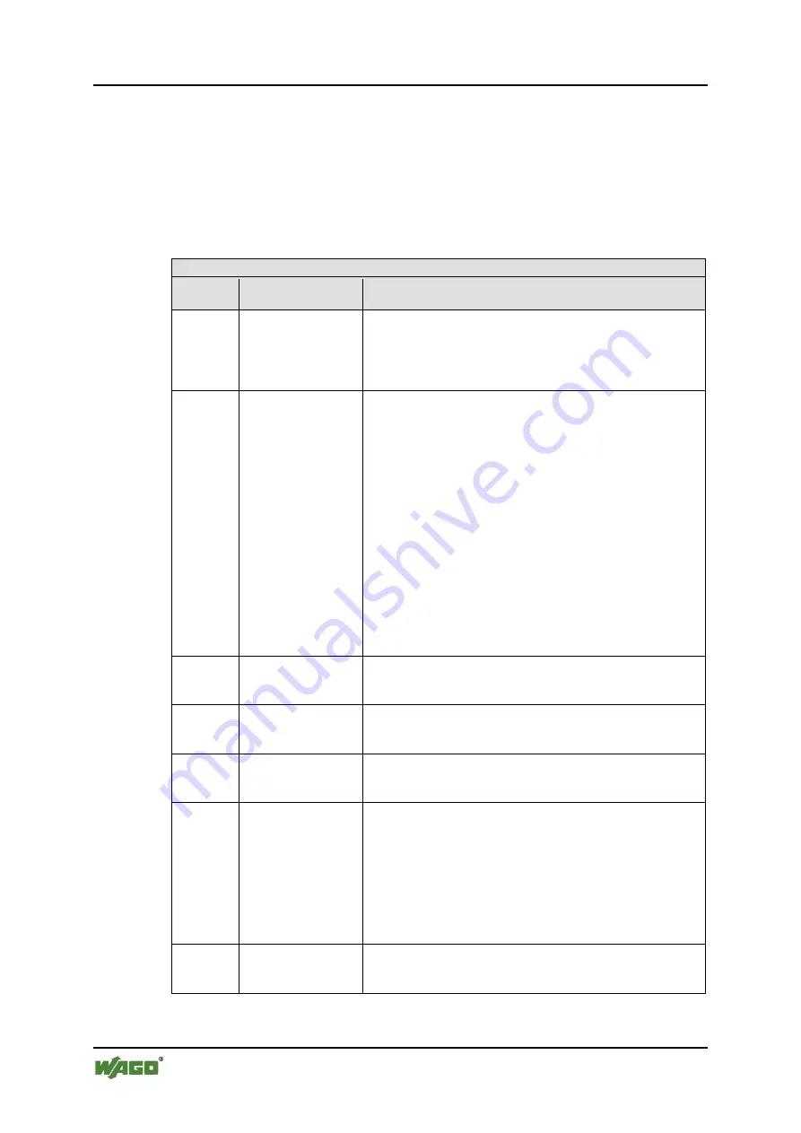
Table 55: Blink Code Table for the 'I/O' LED Signaling, Error Code 1
Error code 1: “Hardware and configuration error”
Error
Argument
Error Description Solution
1
Overflow of the
internal buffer
memory for the
attached I/O
modules.
1. Turn off the power for the node.
2. Reduce the number of I/O modules
3. Turn the power supply on again.
3. If the error persists, replace the fieldbus coupler.
2
I/O module(s) with
unknown data type
Determine the faulty I/O module.
1. Turn off the power supply.
4. Plug the end module into the middle of the node.
5. Turn the power supply on again.
6. --- LED continues to flash? ---
Turn off the power supply and plug the end module into
the middle of the first half of the node (toward the
fieldbus controller).
--- LED not flashing? ---
Turn off the power and plug the end module into the
middle of the second half of the node (away from the
fieldbus controller).
7. Turn the power supply on again.
8. Repeat the procedure described in step 4 while halving
the step size until the faulty I/O module is detected.
9. Replace the faulty I/O module.
10. Inquire about a firmware update for the fieldbus coupler.
3
Invalid check sum in
the parameter area of
the fieldbus coupler.
1. Turn off the power supply for the node.
2. Replace the fieldbus coupler.
3. Turn the power supply on again.
4
Fault when writing in
the serial EEPROM.
1. Turn off the power supply for the node.
2. Replace the fieldbus coupler.
3. Turn the power supply on again.
5
Fault when reading
the serial EEPROM
1. Turn off the power supply for the node.
2. Replace the fieldbus coupler.
3. Turn the power supply on again.
6
The I/O module
configuration after
AUTORESET
differs from the
configuration
determined the last
time the fieldbus
coupler was powered
up.
1. Restart the fieldbus coupler by turning the power supply
off and on.
7
Invalid hardware-
firmware
combination.
1. Turn off the power supply for the node.
2. Replace the fieldbus coupler.
3. Turn the power supply on again.