II 2G IIB T4
Medium pressure
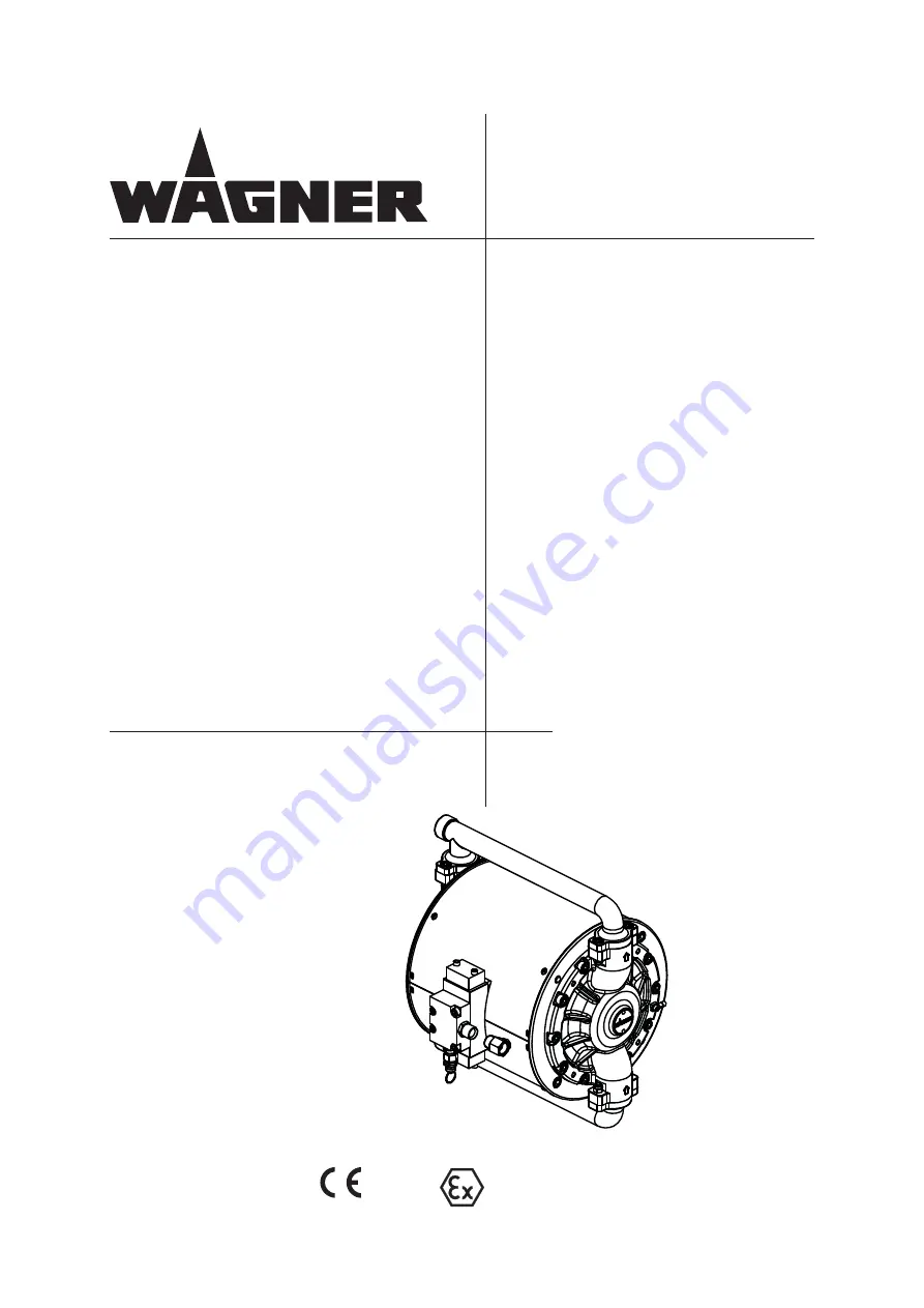
Double diaphragm pump
Unica 4-270 N
Edition 09 / 2015
Translation of the original
Operating Manual
Page 1: ...II 2G IIB T4 Medium pressure Double diaphragm pump Unica 4 270 N Edition 09 2015 Translation of the original Operating Manual ...
Page 2: ......
Page 3: ...4 2 Explosion protection identification 9 2 4 3 Max surface temperature 9 2 4 4 Safety regulations 9 3 PRODUCT LIABILITY AND WARRANTY 11 3 1 Important notes on product liability 11 3 2 Warranty 11 3 3 CE Conformity 12 4 DESCRIPTION 13 4 1 Field of application 13 4 1 1 Using in accordance with the instructions 13 4 1 2 Examples of application areas 13 4 2 Extent of delivery 14 4 3 Data 14 4 3 1 Mat...
Page 4: ...6 2 2 Washing and storing 33 6 2 3 Regular check of sealing and tightness 33 6 2 4 Plan of preventive maintenance 33 6 3 Pump repair 34 6 3 1 Maintenance of the hydraulic circuit 34 6 3 1 1 Operations on the hydraulic circuit during maintenance 36 6 3 1 2 Hydraulic circuit emptying 36 6 3 1 3 Hydraulic circuit filling 36 7 ACCESSORIES 37 7 1 Wall mounting kit 37 7 2 Stand kit 38 7 3 Compressed air...
Page 5: ...ZARDOUS SITUATION ON OBSER VANCE CAN RESULT IN MINOR INJURY OTE PROVIDE INFORMATION ON PARTICULAR CHARACTERISTICS AND HOW TO PROCEED AUTION A POSSIBLY HAZARDOUS SITUATION ON OBSER VANCE CAN CAUSE MATERIAL DAMAGE 3 2 4HIS LINE WARNS OF THE HAZARD 0OSSIBLE CONSEQUENCES OF FAILING TO OBSERVE THE WARNING INSTRUC TIONS 4HE SIGNAL WORD POINTS OUT THE HAZARD LEVEL 4HE MEASURES FOR PREVENTING THE HAZARD A...
Page 6: ...CTIVE PARTS NFORM STAFF ABOUT PLANNED WORK OBSERVE ELECTRICAL SAFETY REGULATIONS NSURE THAT THE UNIT IS OPERATED AND REPAIRED ONLY BY TRAINED PERSONS LWAYS FOLLOW THE INFORMATION IN THESE INSTRUCTIONS PARTICULARLY THE GENERAL SAFETY IN STRUCTIONS AND THE WARNING INSTRUCTIONS LWAYS FOLLOW LOCAL REGULATIONS CONCERNING OCCUPATIONAL SAFETY AND ACCIDENT PREVEN TION NSURE THAT THE mOOR OF THE WORKING AR...
Page 7: ...IMMEDIATELY VOID DANGER OF INJURY THROUGH RECOIL FORCES NSURE THAT YOU HAVE A lRM FOOTING WHEN OPERATING THE SPRAY GUN NLY HOLD THE SPRAY GUN BRIEmY IN ANY ONE POSITION LECTROSTATIC CHARGES CAN OCCUR ON THE UNIT DUE TO THE ELECTROSTATIC CHARGE AND THE mOW SPEED INVOLVED IN SPRAYING 4HESE CAN CAUSE SPARKS AND mAMES UPON DISCHARGE NSURE THAT THE UNIT IS EARTHED FOR EVERY SPRAYING OPERATION ARTH THE ...
Page 8: ...F THE PAINTS SOLVENTS AND CLEANING AGENTS BEING USED 4AKE THE SPECIlED PROTECTIVE MEASURES IN PARTICULAR WEAR SAFETY GOGGLES PROTECTIVE CLOTHING AND GLOVES AS WELL AS HAND PROTECTION CREAM IF NECESSARY 5SE A MASK OR BREATHING APPARATUS IF NECESSARY OR SUFlCIENT HEALTH AND ENVIRONMENTAL SAFETY PERATE THE UNIT IN A SPRAY BOOTH OR ON A SPRAYING WALL WITH THE VENTILATION EXTRACTION SWITCHED ON 7EAR SU...
Page 9: ...urface temperature 135 C 275 F Max surface temperature same as the permissible material temperature Permissible ambient temperature see under Technical data Section 4 3 2 Safe handling of WAGNER spray units Internal explosive zone can be generated if the pump runs dry J Ensure that the pump is filled with sufficient working or cleaning medium Mechanical sparks can form if the unit comes into contact...
Page 10: ...TO MAINTAIN CONDUCTIVITY 5SE ONLY A DAMP CLOTH TO CLEAN THE UNIT 3URFACE SPRAYING ELECTROSTATIC O NOT SPRAY UNIT PARTS WITH ELECTROSTATIC E G ELECTROSTATIC SPRAY GUN WARNING Gas mixtures can explode if there is an incompletely filled pump Danger to life from flying parts J Ensure that the pump and suction system are always completely filled with cleaning agent or working medium J Do not spray the uni...
Page 11: ...OF THE UNIT TO A LOCATION OTHER THAN THE ADDRESS OF THE PURCHASER 4HIS WARRANTY DOES NOT COVER DAMAGE CAUSED BY 5NSUITABLE OR IMPROPER USE FAULTY INSTALLATION OR COMMISSIONING BY THE PURCHASER OR A THIRD PARTY NORMAL WEAR NEGLIGENT HANDLING DEFECTIVE MAINTENANCE UNSUITABLE COATING PRODUCTS SUBSTITUTE MATERIALS AND THE ACTION OF CHEMICAL ELECTROCHEMICAL OR ELECTRICAL AGENTS EXCEPT WHEN THE DAMAGE I...
Page 12: ...IVE QUOTING THE PRODUCT AND SERIAL NUMBER 0ART NUMBER Complies with the following directives applying to it 2006 42 EC 94 9 EC Atex directives Applied standards in particular UNI EN ISO 12100 1 UNI EN 809 UNI EN 1127 1 UNI EN ISO 12100 2 UNI EN 14121 1 EN 12621 UNI EN 563 UNI EN ISO 3746 UNI EN ISO 13463 1 Marking Unica 4 270 ZDI 15 Herewith we declare that the supplied version of Pneumatic pump w...
Page 13: ... the materials used for the fluid section Paragraph 4 3 1 4 1 2 EXAMPLES OF APPLICATION AREAS The main use of the Unica 4 270 N pump is for fluid transfer inside service circuits Other typical applications are given below Application Unica 4 270 N Furniture industry Kitchen manufactures Joinery Wooden cowls manufacturers Metal industries Legend recommended limited suitability less suitable 54 BRAS...
Page 14: ...28ENG Operating manual for other languages see Chapter 1 1 The delivery note shows the exact scope of delivery Accessories see chapter 7 4 3 DATA 4 3 1 MATERIALS USED FOR COMPONENTS IN CONTACT WITH THE PRODUCT Suction ducts Stainless steel EN 1 4301 X 5 CrNi 18 10 AISI 304 Valves balls Stainless steel EN 1 4028 X 30 Cr 13 AISI 420 Valves seats Stainless steel EN 1 4301 X 5 CrNi 18 10 AISI 304 Valv...
Page 15: ...d air hose mm Inch 13 0 512 Air consumption at 0 6 MPa 6 bar 87 psi per DS nl scf 16 Noise level with max allowable air supply pressure dB A 77 5 Ø piston of air motor mm Inch 200 8 0 Material inlet connection female Zoll Inch G 3 4 Material outlet connection female Zoll Inch G 3 4 Weight kg lb 46 101 2 Material pH value pH 3 5 9 Max material pressure at pump inlet MPa bar psi 2 20 90 Range of mat...
Page 16: ...NG 7 2 UTGOING AIR CONTAINING OIL 2ISK OF POISONING IF INHALED UNCTION PROBLEM AIRMOTOR 0ROVIDE WATER FREE AND OIL FREE COMPRESSED AIR QUALITY STANDARD AS PER 3 M MG MÃ 3 Description Unit Unica 4 270 N Dry suction height m ft 4 13 1 Liquid suction height m ft 8 26 2 ...
Page 17: ... L Unica 4 270 N mm inch Unica 4 270 N mm inch A 362 14 3 G 209 8 2 B 83 3 3 H 164 6 5 C 422 16 6 I 412 16 2 D 180 5 7 1 J G 3 4 E 171 5 6 8 K G 3 4 F 384 15 1 L G 1 2 OPERATING MANUAL EDITION 09 2015 PART NO ZZB028ENG 4 3 3 DIMENSIONS AND CONNECTIONS ...
Page 18: ...4 bar C_41_00003 2 bar 2 bar OPERATING MANUAL EDITION 09 2015 PART NO ZZB028ENG Diagram Unica 4 270 N Stroke frequency DS min Material pressure Air consumption Material flow volume water A 6 bar 0 6 MPa 87 psi Air pressure B 4 bar 0 4 MPa 58 psi Air pressure C 2 bar 0 2 MPa 29 psi Air pressure 4 3 4 PERFORMANCE DIAGRAMS Example Stroke frequency DS min Material pressure bar MPa psi Material flow vo...
Page 19: ...at the same time Pneumatic motor Thanks to its reversing system 3 the pneumatic motor needs no lubrication The compres sed air supply is obtained by a pressure reducer and a ball valve available on request with the pump The pneumatic motor is equipped with a safety valve containing a pre loaded spring The safety valve is mounted and calibrated in the factory When the pressure exceeds the max allow...
Page 20: ...egulator 2 Control air gauge 3 Motor air shut off valve Fluid section The fluid section has been designed to work as a double diaphragm pump with interchan geable suction and delivery valves WARNING Overpressure Risk of injury from bursting components SIHC_0026_GB Frequently check the safety valve efficiency by pulling the ring ...
Page 21: ...upport about how to integrate the pump in a pre existing plant or for a customised location please refer to a Wagner authorised technician Always use original Wagner spare parts 5 1 1 PUMP WALL MOUNTING INSTALLATION The Unica 4 270 N pump installation kit for wall mounting can be supplied on request Part number Wall mounting kit T6151 00 For any information regarding the kit s content and assembli...
Page 22: ...downstream the pressure controller this allows to open shut off the air flow supplying the pneumatic motor 5 1 4 SUCTION CIRCUIT Use electrically conductive pipes see Paragraph 2 2 3 Connect the working fluid suction system to the pump by means of a system of pipes and fittings E For the correct pump inlet thread diameters please see Paragraph 4 3 2 Tech nical Data Use a system of pipes suitable f...
Page 23: ...23 Unica 4 270 N OPERATING MANUAL EDITION 09 2015 PART NO ZZB028ENG 5 1 6 EXAMPLE OF TYPICAL INSTALLATION C_41_00011 F B A E C D H G S462 00A L I ...
Page 24: ...lly charged components in atmo spheres containing solvents Explosion hazard from electrostatic sparks Clean the pump only with a damp cloth SIHC_41_0041_GB 7 2 EAVY PAINT MIST IF EARTHING IS INSUFlCIENT 2ISK OF POISONING NSUFlCIENT PAINT APPLICATION QUALITY ARTH ALL UNIT COMPONENTS ARTH THE WORKPIECES BEING PAINTED 3 Paint container Workpiece Conveyor Anti static floor Pump Spraying stand ...
Page 25: ...WG 10 Conveyor 16 mm AWG 5 Spraying booth 16 mm AWG 5 Spraying stand 16 mm AWG 5 Procedure 1 Screw on earthing cable with eyelet terminal 2 Clamp the earthing cable clip to a earth connection on site 3 Earth the material paint container to a local earth connection 4 Earth the other parts of the system to a local earth connection ...
Page 26: ...AUSED BY PAINT OR SOLVENT NFORM THE DOCTOR ABOUT THE PAINT OR SOLVENT USED EVER SEAL DEFECTIVE HIGH PRESSURE PARTS INSTEAD RELIEVE THE PRESSURE FROM THEM AND REPLACE 3 7 2 4OXIC AND OR mAMMABLE VAPOR MIXTURES 2ISK OF POISONING AND BURNS PERATE THE UNIT IN A SPRAYING BOOTH APPROVED FOR THE WORKING MATERIALS OR PERATE THE UNIT ON AN APPROPRIATE SPRAYING WALL WITH THE VENTI LATION EXTRACTION SWITCHED...
Page 27: ... the compressed air sup ply and discharge the pressure from the pump service circuit 5 2 2 PRESSURE RELEASE PROCEDURE 1 Interrupt the pump compressed air supply 2 Open the usage and discharge the remaining pressure inside the pump and circuit 3 To guarantee a complete depressurisation of the pneumatic motor pull the ring of the safety valve see Paragraph 4 4 1 5 2 3 PUMP WASHING The Unica 4 270 N ...
Page 28: ... the pump D 6 Slowly open the air pressure regulator on the pump C until it starts working Have the pump work slowly until all the air left inside the suction and delivery circuits has been discharged Continue until the pump has correctly primed 7 Only if the pump is being washed with solvent have it cycle until the clean solvent flows inside the delivery circuit Then close the pump air pressure c...
Page 29: ...WITH SOLVENTS AND CAN BURST LYING PARTS CAN CAUSE INJURY O NOT CLEAN THE CONTAINER ON THE PRESSURE REGULATOR WITH SOL VENT 3 WARNING Gas mixtures can explode if there is an incompletely filled pump Danger to life from flying parts J Ensure that the pump and suction system are always completely filled with cleaning agent or working medium J Do not spray the unit empty after cleaning SIHI_41_0025_GB 5 ...
Page 30: ...umatic delivery plant In painting applications obstruction of the cartidge filter inside spray gun or of the high pressure filter Clean the parts and use a suitable working material Obstruction of the pump fluid section or of the high pressure pipes for example hardened products inside the delivery pipes Dismantle the pump and clean replace high pressure hose Excess of grease or dirt inside the re...
Page 31: ...ilter or working air filter Check filters and if necessary clean them The pump doesn t work pneumatic motor stall Insufficient diameter of compressed air feeding hose Push the anti stall rod to unblock the pneumatic motor Use a pneumatic feeding hose having a larger diameter Paragraph 4 3 2 Technical data Piloting system air supply hose wrongly assembled after the pump air pressure regulator Push ...
Page 32: ...ctions on the suction system leak and the pump sucks air Tighten the fittings and remove leaks Obstructed suction filter Clean filter Obstructed suction valves Clean the pump fluid section with detergent and if necessary let the detergent act for some time in case purge the device The pump runs when the gun is closed Packings valves worn Replace parts Loss of power due to ice formation in the pneu...
Page 33: ... Make sure there are no leaks Check screws tightness at least once every two months Please see this manual for information about the correct tightening torques 6 2 4 PLAN OF PREVENTIVE MAINTENANCE Work out a plan of preventive maintenance including the above checks basing on the usage history of the pump The wear of components depends on the using conditions It is important to replace the parts su...
Page 34: ... MAINTENANCE OF THE HYDRAULIC CIRCUIT The Unica 4 270 N pump includes a fluid mechanical conservation system granting the best possible performance of the diaphragms under normal working conditions The hydraulic circuit is normally full of working fluid filled in the factory The safety card of the working fluid can be supplied on request Before carrying out any maintenance involving the hydraulic ...
Page 35: ...35 Unica 4 270 N OPERATING MANUAL EDITION 09 2015 PART NO ZZB028ENG Cap Outlet valve Working fluid ...
Page 36: ...and the following operations are not necessary If the maintenance in the fluid section concerns components whose access to or disas sembly of require the disassembling of the pump covers picture Paragraph 8 5 then the following operations emptying and filling up the hydraulic circuit with working fluid are necessary If the maintenance concerns the pneumatic motor or the hydraulic circuit itself th...
Page 37: ...Qty Description No Wall mounting kit T6151 00 1 4 Washer K509 62 2 2 Wall bracket E3239 62 3 4 Contact washer K572 62 4 4 M8x18 screw K136 62A Wearing part NOTE If you are not going to use the original screws 4 included in the frame kit make sure not to use too long screws that could damage the sealing of the pump external covers ...
Page 38: ...K Qty Description No Stand kit T6148 00 1 2 Stand frame E3238 92 2 8 Contact washer K572 62 3 8 M8x70 screw K193 62 Wearing part NOTE If you are not going to use the original screws 3 included in the frame kit make sure not to use too long screws that could damage the sealing of the pump external covers ...
Page 39: ...RESSED AIR SUPPLY KIT Pos K Qty Description No Compressed air supply kit T6152 00 1 1 Air cut off valve M104 00 2 1 Nipple M206 04 3 1 Pressure regulator 9999506 4 1 Reduction unit M203 04 5 1 Pressure gauge P903 00 6 1 Hose nylon d4 L 370 mm S462 00A 7 1 Nipple M631 62 8 1 Fitting M652 00 Wearing parts ...
Page 40: ...NUAL EDITION 09 2015 PART NO ZZB028ENG 7 4 SPRING KIT FOR PRODUCT VALVES Pos K Qty Description No 1 Spring kit Unica 4 270 N T6169 00 1 4 Valve guide B0373 07 2 4 Spring H293 03 3 4 PTFE O ring seal L228 05 4 4 PTFE O ring seal L227 05 Wearing parts ...
Page 41: ...TION 09 2015 PART NO ZZB028ENG 7 5 SUCTION HOSE KIT Pos K Qty Description No 1 Suction hose kit Unica 4 270 N T4021 00I 1 1 Stainless steel reduced nipple M812 03B 2 1 Stainless steel suction pipe T409 00EI 3 1 Stainless steel filter 0250245 Wearing parts ...
Page 42: ...EQUIRED AIR FREIGHT OR MAIL SEA ROUTE OR OVERLAND ROUTE ETC ARKS IN SPARE PARTS LISTS OTE TO COLUMNu h IN THE FOLLOWING SPARE PARTS LISTS U 7EARING PARTS OTE O LIABILITY IS ASSUMED FOR WEARING PARTS L OT PART OF STANDARD EQUIPMENT AVAILABLE HOWEVER AS ADDITIONAL EXTRA 8 SPARE PARTS 8 1 HOW TO ORDER SPARE PARTS 3 7 2 NCORRECT MAINTENANCE REPAIR 2ISK OF INJURY AND DAMAGE TO THE EQUIPMENT 2EPAIRS AND...
Page 43: ...43 Unica 4 270 N OPERATING MANUAL EDITION 09 2015 PART NO ZZB028ENG ...
Page 44: ... 2015 PART NO ZZB028ENG 8 2 OVERVIEW MODULES Hydraulic circuit Ref Par 6 3 1 Fluid section Fluid section Air motor Pos K Qty Description No 1 16 5x8 screw K1072 03 2 8 Contact washer K571 62 3 1 Pump upper protection E3235 71 4 1 Pump lower protection E3236 71 Wearing parts ...
Page 45: ... 18 5 a 3 a 1 20 a 50 Nm 37 lbft 6 4 4 C_41_00030 26 27 28 25 7 15 14 14 14 24 15 Nm 11 1 lbft 19 10 11 22 20 a 50 Nm 37 lbft 2 1 4 3 a 6 4 14 15 25 16 22 22 14 15 18 17 18 21 14 15 25 14 22 OPERATING MANUAL EDITION 09 2015 PART NO ZZB028ENG 8 3 AIR MOTOR a Apply a small quantity of grease ...
Page 46: ...l nipple 1 2 M206 04 13 4 M8x75 SS Socket screw K106 62 14 5 Fast fitting L 1 8x4 M335 00 15 2 Hose nylon d4 L 130 mm S462 00 16 1 Fast fitting T 1 8 x4 M348 00 17 1 Hose PU d14x10 L 210 mm S463 00 18 2 Fast fitting L 1 2x14 M415 00 19 2 Lip seal L481 06 20 2 Pump rod D450 03A 21 1 Hose PU d14x10 L 610 mm S463 00A 22 1 Hose nylon d4 L 370 mm S462 00A 23 Loctite 542 50ml 50cc Z201 00 24 1 Pneumatic...
Page 47: ...y Description No Pneumatic feeler T714 00 1 1 Feeler cap B0331 04 2 1 NBR O Ring seal L118 06 3 1 Seal gasket L420 06 4 1 Feeler rod B0333 03 5 1 Feeler body B0332 04 6 1 NBR O Ring seal L230 06 7 1 Seal gasket G602 06 8 1 Feeler shutter A144 04 9 1 Feeler spring H202 03 10 Loctite 601 50ml 50cc Z203 00 Wearing parts Included in motor service set T9089 00 ...
Page 48: ...scription No Reversing valve P497 00A 1 4 Socket screw K183 62 2 1 Rod cover B0055 71A 3 2 Cover seal gasket G7010 07B 4 1 O Ring seal L172 06 5 1 Rod B0049 04B 6 2 Damper P519 00A 7 1 Valve body B0053 71A 8 6 O Ring seal L199 06 9 1 Spool assembly P519 00B 10 1 Detent P519 00E 11 1 Detent cap B0054 71A 12 1 Valve seal gasket G737 06BA 13 1 Pos seal gasket set 3 4 6 8 12 T9076 00A ...
Page 49: ...RT NO ZZB028ENG 8 4 HYDRAULIC CIRCUIT Hydraulic fluid compartment Ref Par 6 3 1 REMARK The hydraulic circuit is normally full of working fluid filled in the factory In case of disassembly of the hydraulic circuit the fluid is to be previously extracted as indicated in the instructions given in Paragraph 6 3 1 and later refilled Part 4 Pneumatic Motor unit Rif Par 8 3 Part 4 Pneumatic Motor unit Re...
Page 50: ...137 06A 8 2 Slip band L823 08 9 2 Lip seal L481 06 10 4 Fast fitting 1 2x14 M415 00 11 2 Bleed plug M071 07 12 2 Check valve T6199 00 13 2 NBR O Ring seal L225 06 15 2 Inner flange F1013 71 16 2 Reduction unit 3 4x1 2 M427 00 17 1 Hose PU d14x10 L 210 mm S463 00 18 2 Bellows flange 2 parts B0334 03 1 Hydraulic fluid 1L bottle Z126 00 Wearing parts Included in the cpl hydraulic circuit service set ...
Page 51: ...6 5 21 21 28 28 10 11 5 7 6 8 4 16 12 13 14 26 4 6 8 5 7 4 6 8 5 7 15 24 25 OPERATING MANUAL EDITION 09 2015 PART NO ZZB028ENG 8 5 FLUID SECTION The diaphragms are the outer walls of the hydraulic cir cuit which is normally filled with working fluid Before re moving them extract the fluid as described in Paragraph 6 3 1 ...
Page 52: ...4 Self threading rivet K1041 62A 11 2 Plate Z5026 00 12 1 Anti rotation bracket E0042 62 13 1 Eyelet terminal Y622 00B 14 1 Square nut 6 K343 62A 15 1 Grub screw 6x25 K040 02D 16 2 Outer cover F1014 03 21 2 Diaphragm G930 07C 22 1 Suction manifold F1015 03A 23 Loctite 542 50ml 50cc Z201 00 24 1 Washer K562 02 25 1 Nut 6 K316 62 26 1 Stick label Z510 00 28 2 Flat gasket G7041 06 Wearing parts Inclu...
Page 53: ...53 Unica 4 270 N OPERATING MANUAL EDITION 09 2015 PART NO ZZB028ENG ...
Page 54: ... fr Netherlands WAGNER SPRAYTECH Benelux BV Zonnebaan 10 NL 3542 EC Utrecht PO Box 1656 3600 BR Maarssen Telephone 31 0 30 241 4155 Telefax 31 0 30 241 1787 E Mail info wagner group nl Italy WAGNER COLORA S r l Via Italia 34 I 20060 Gessate MI Telephone 39 02 9592921 Telefax 39 02 95780187 E Mail info wagnercolora com Japan WAGNER Spraytech Ltd 2 35 Shinden Nishimachi J Daito Shi Osaka 574 0057 Te...
Page 55: ......
Page 56: ...7 2 MB TTO ILIENTHAL 3TR 0OSTFACH ARKDORF 4ELEPHONE 4ELEFAX AIL SERVICE STANDARD WAGNER GROUP COM 3WITZERLAND 7 2 NDUSTRIESTRASSE 0OSTFACH LTSTËTTEN 4ELEPHONE 4ELEFAX AIL REP CH WAGNER GROUP CH WWW WAGNER GROUP COM ZZB028ENG ...