background image

65

VERSION 01/2018

ORDER NUMBER DOC 2385674

TOPFINISH Bell 1S

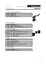
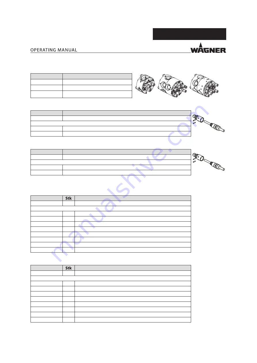
14.6  VALVE BLOCKS

Order no.

Description

B_06866

1

2

4

2372279

Valve block M/DM/FB (1-paint)

2391613

Valve block 2C (2-paints)

2391617

Valve block 4C (4-paints)

14.7  OPTICAL FIBER 9.9 M WITH SLEEVE

Order no.

Designation

B_06679

2383286

Optical fiber 9.9 m with sleeve

Consists of:

2335584

Optical fiber 9.9 m

2382097

Sleeve for optical fiber, complete

14.8  OPTICAL FIBER 15 M WITH SLEEVE

Order no.

Designation

B_06679

2383289

Optical fiber 15 m with sleeve

Consists of:

387101

Optical fiber 15 mm

2382097

Sleeve for optical fiber, complete

14.9  HOSE SETS
14.9.1 AIR HOSE SET, 10 M

Order no.

Designation

2373986

Air hose set, 10 m

consisting of:

700370

5

Hose PU ø 8/5.5 mm blue 10 m

700371

1

Hose PU ø 6/4 mm blue 10 m

2348719

4

Hose PEN ø 4/2.7 mm blue 10 m

2383812

1

Wire labeling

3051200

2

Cable tie 360x4.8 mm

3051199

2

Cable tie 140x3.6 mm

9982016

1

Protective hose 9m

2335584

1

Optical fiber 9.9 m

14.9.2 AIR HOSE SET, 15 M

Order no.

Designation

2373994

Air hose set, 15 m

consisting of:

700370

5

Hose PU ø 8/5.5 mm 15 m

700371

1

Hose PU ø 6/4 mm blue 15 m

2348719

4

Hose PEN ø 4/2.7 mm blue 15 m

2383812

1

Wire labeling

3051200

2

Cable tie 360x4.8 mm

3051199

2

Cable tie 140x3.6 mm

9982016

1

Protective hose 14m

387101

1

Optical fiber 15 mm

Summary of Contents for TOPFINISH Bell 1S

Page 1: ...TOPFINISH Bell 1S High speed rotary atomizers for reciprocators Version 01 2018 II 3G T6 X B_ 06668...

Page 2: ......

Page 3: ...X 13 3 3 Type plate 14 4 BASIC SAFETY INSTRUCTIONS 15 4 1 Safety Instructions for the Operator 15 4 1 1 Electrical Devices and Equipment 15 4 1 2 A Safe Work Environment 15 4 1 3 Personnel Qualificat...

Page 4: ...oduct supply lines 38 6 8 Grounding 38 6 9 Commissioning 40 6 9 1 Presettings 40 6 9 2 Safety Checks 40 6 9 3 Lacquer Preparations 40 6 9 4 Viscosity conversion table 40 6 9 5 Operating Instructions f...

Page 5: ...ction Intervals in Accordance with Table 4 of DIN EN 50176 2010 04 62 13 2 Inspections in Accordance with DIN EN 50348 63 13 2 1 Overview of Inspections 63 13 2 2 Inspection Intervals in Accordance wi...

Page 6: ...9 15 2 Spare Parts List for TOPFINISH Bell 1S 70 15 3 O Ring Set Air Deflector Ring 73 15 4 O Ring Set Product Tube 73 15 5 O Ring Set Air Bearing 73 15 6 Bolt Set 73 16 EU DECLARATION OF CONFORMITY 7...

Page 7: ...SYMBOLS IN THESE INSTRUCTIONS Warning instructions in this manual highlight particular dangers to users and to the device and state measures for avoiding the hazard These warning instructions fall in...

Page 8: ...structed in the tasks assigned to him her the potential risks associated with improper behavior as well as the necessary protective devices and measures Electrically trained person Is instructed by an...

Page 9: ...ary atomizer to the cascade Cascade High voltage generator Bearing air BA Air inlet on rear of air bearing for mounting the motor Steering air SA Steering airs SA1 SA2 are air inlets on the rear of th...

Page 10: ...ecommended by WAGNER Do not deactivate safety fixtures Use only WAGNER original spare parts and accessories The operating personnel must be trained on the basis of this operating manual 2 3 FOR USE IN...

Page 11: ...ay current A High kV value low A value no wrap around Paint with excessive electrical resistance Low kV value high A value no wrap around Excessive conductivity of the paint With a non grounded lacque...

Page 12: ...s in this group have the following composition wt H2 O 1 50 x wt LM 0 49 x wt ORG Spray patterns of these lacquers cannot be ignited by sparks with an energy 4 J Explosion protection in the spray area...

Page 13: ...ent temperature have been listed in the 5 4 2 Technical Data chapter Safe Handling of WAGNER Spray Devices Mechanical sparks can form if the device comes into contact with metal In an explosive atmosp...

Page 14: ...3G T6 X Check manual before use Admissible combinations of devices see information for use 0 8MPa 116psi 0 8MPa 116psi 0 55MPa 80psi 80 000rpm 50 C 122 F 0 Ta 40 C 32 F Ta 104 F W 350mJ B_06861 1 2 3...

Page 15: ...ective ground wire connection Keep liquids away from electrical devices 4 1 2 A SAFE WORK ENVIRONMENT Hazard due to dangerous fluids or vapors Severe or fatal injuries due to explosion hazard or inhal...

Page 16: ...NSTRUCTIONS FOR THE PERSONNEL Always follow the information in this manual particularly the safety instructions and the warning instructions Always follow local regulations concerning occupational saf...

Page 17: ...ces DGUV German Statutory Accident Insurance regulation 100 500 chapters 2 29 and 2 36 For shut down devices the examination can be suspended until the next start up Carry out the work steps as descri...

Page 18: ...parts or on hot surfaces Ensure that the hoses are never run over by vehicles e g fork lifts or that the hoses are never put under pressure from the outside in any other way Ensure that the hoses are...

Page 19: ...r emptying the device please note that depending upon the coating product used depending on the flushing agent solvent used an explosive mixture may temporarily exist inside the lines and components o...

Page 20: ...apter 14 and that are assigned to the unit Before all work on the device and in the event of work interruptions Relieve the pressure from the high speed rotary atomizer and all devices Secure the high...

Page 21: ...ignation 1 Distributor 8 Optical fiber 2 Bell 9 Transition flange 3 Product nozzle screwed together with the product tube item 6 10 Valve block 4 Air control ring 11 Casing 5 Bearer ring 12 Union nut...

Page 22: ...re product channel If working with water based lacquer the system is linked to the rest of the system via the lacquer pillar ion conductor such that the paint supply has to be isolated as well 5 2 1 F...

Page 23: ...ough the central drill hole of the product tube The spray pattern is formed with the steering airs 1 Steering air SA1 outer air for shaping Steering air SA2 inner air to advance the product Flushing a...

Page 24: ...manual German 1 see Chapter 1 3 Operating manual in local language The high speed rotary atomizer consists of the premounted basic device as well as the accessories required explicitly for this purpos...

Page 25: ...psi Average steering air consumption 200 nl min 7 06 scfm Maximum steering air consumption 450 nl min 15 89 scfm Product pressure Typically 50 200 kPa max 800 kPa Typically 7 29 psi max 116 psi Typica...

Page 26: ...202 100 ca 314 346 7 30 82 94 113 5 4 4 AIR CONSUMPTION Air consumption of steering airs Pressure bar Steering air SA1 nl min Steering air SA2 nl min 0 5 65 59 1 0 111 105 1 5 155 154 2 0 202 205 2 5...

Page 27: ...m 0 157 inch 4 Bearing air monitoring BAM 4 mm 0 157 inch 5 Stop air STA 8 mm 0 315 inch 6 Return dump DM 5 8 mm 0 197 0 315 inch 7 Bearing air BA 8 mm 0 315 inch 8 Control air dump CA DM 4 mm 0 157 i...

Page 28: ...ing 1 F1 4 8 mm 0 157 0 315 inch 8 Bearing air BA 8 mm 0 315 inch 9 Bearing air monitoring BAM 4 mm 0 157 inch 10 Product 1 M1 4 mm 0 157 inch 11 Dump 1 DM1 6 9 mm 0 236 0 354 inch 12 Drive air DA 8 m...

Page 29: ...m 0 157 inch 9 Bearing air monitoring BAM 4 mm 0 157 inch 10 Bearing air BA 8 mm 0 315 inch 11 Product 4 M4 5 8 mm 0 196 0 315 inch 12 High voltage HV 13 Steering air 2 inner holes SA2 8 mm 0 315 inch...

Page 30: ...air DA 8 mm 0 315 inch 6 Steering air 1 outer holes SA1 8 mm 0 315 inch 7 Turbine air venting EX2 12 mm 0 472 inch Steering air 2 inner holes not visible in this figure SA2 8 mm 0 315 inch 5 4 9 CONNE...

Page 31: ...ORAGE CONDITIONS Until the point of assembly the device must be stored in a dry location free from vibrations and with a minimum of dust The device must be stored in closed rooms The air temperature a...

Page 32: ...ve supplied by the customer if required If necessary this shut off valve could be shut off if a fire alarm sounds or under other conditions The air supply to the bearing air on the other hand must be...

Page 33: ...idual needs The high speed rotary atomizing system may only be commissioned by trained and skilled specialistpersonnel Ensurethattheoperatingpersonnelhavefamiliarizedthemselveswith the additional oper...

Page 34: ...lude a safe shutdown after the first spark discharge at the latest DANGER Exploding gas air mixture due to a sparkover Danger to life from flying parts and burns Ground all device components Ground th...

Page 35: ...check that sparkovers do not occur The attachment point for the TOPFINISH Bell 1S is not grounded Failure to observe the distances may result in high voltage sparkover damage and greater contaminatio...

Page 36: ...ropriate length b Pre assembled high voltage cable high voltage cable and connector plug see Chapter 14 11 of appropriate length c Optical fiber see Chapter 14 7 14 8 d Product line of the appropriate...

Page 37: ...p return line DM 11 Connect the product hoses for the product supply line M 12 Connect the product hoses for the flushing agent supply line FB 13 Connect the air hoses for controlling to all the valve...

Page 38: ...ray will be collected up safely 6 7 3 AIR SUPPLY LINES Ensure that only dry clean atomizing air penetrates the high speed rotary atomizer Dirt and moisture in the atomizing air worsens the spraying qu...

Page 39: ...g and coating are clean suspension for the workpiece to be coated grounding of spray booth conveyor system and suspension equipment on the building side in accordance with the operating manuals or the...

Page 40: ...quer is of great importance Adjust the viscosity according to the application The best spraying results are obtained with values between 15 and 30 DIN 4 seconds measured in immersion flow cup DIN 4 mm...

Page 41: ...he drive turbine Incorrect handling causes damage to the drive turbine Ensure that bearing air is applied before commissioning during after operation of the atomizer and up until the drive turbine has...

Page 42: ...ld be checked by briefly turning the spindles by hand If the spindle cannot be turned with ease the bearing air setting should be checked again 3 Set product pressure to 0 1 MPa 1 0 bar 14 50 psi 4 Pu...

Page 43: ...e product for 1 minute or twice for 30 seconds 7 Compare the calculated application rate with the table 8 If the application rate is too low you may need to use a larger bell plate Notice When calibra...

Page 44: ...r can be adapted individually by modifying the steering air SA Advancement kinetic energy via steering air 2 shape of the spray pattern small large via steering air 1 Larger or smaller spray patterns...

Page 45: ...he high speed rotary atomizer The components for pressure relief on a CE compliant spray system include Air cock with pressure relief hole mounted between compressed air source and pneumatic pump Prod...

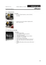
Page 46: ...tting There may be no gap at the rear of the union nut 7 4 2 CHANGING AIR CONTROL RING B_06681 Procedure 1 Unscrew union nut from air ring by hand or with hook wrench and remove it 2 Press and hold do...

Page 47: ...sen Allen screws on carrier ring and unscrew 6 Pull off carrier ring 7 Fit another carrier ring tightening torque 1 Nm 0 74 lb ft 8 Slide air control ring onto carrier ring 9 With locking button press...

Page 48: ...zzle 10 Fit carrier ring tightening torque 1 Nm 0 74 lb ft 11 Slide air control ring onto carrier ring 12 With locking button pressed and held screw on bell plate and check for firm seating 13 Slide u...

Page 49: ...the high speed rotary atomizer down when cleaning Ensure that neither paint nor flushing agent enters the air duct Never immerse the high speed rotary atomizer in cleaning agent The high speed rotary...

Page 50: ...product or solvent may leak out or escape 6 Wipe down outside of high speed rotary atomizer with a cloth and suitable cleaning agent Notice Do not use abrasive agents 7 Dry outside of high speed rotar...

Page 51: ...re assigned to the unit Before all work on the device and in the event of work interruptions Relieve the pressure from the high speed rotary atomizer high pressure hoses and all devices Secure the hig...

Page 52: ...to check the condition of the high speed rotary atomizer The checks needed are described in the tables below Location Description Inspection interval Type of inspection Inspection criteria Spray boot...

Page 53: ...nding Check weekly Measurement The grounding resistance of the work piece must not exceed 1 M Spray booth Check linkage weekly Visual inspection Check linkage for contamination Spray booth Contaminati...

Page 54: ...izer Speed control monthly Function test Does the speed control quickly control the speed Supply Product supply lines monthly Visual inspection Product supply lines not damaged Supply Product supply l...

Page 55: ...eed rotary atomizer Check routing of air hose for bearing air BA Product and or solvent in the air bearing Check product and solvent pressure Exhaust opening on the bell plate clogged Repair or replac...

Page 56: ...e control cabinet is locked internally Activate release for supply and exhaust air Ventilation hole blocked Clean ventilation hole Product valve M on valve block closed Ensure product release The high...

Page 57: ...SA2 0 04 MPa 0 4 bar 5 80 psi Insufficient grounding of work piece Check grounding connection 9 4 SPRAY PATTERN GEOMETRY Functional fault Cause Remedy Spray pattern too wide Air control ring dirty Cle...

Page 58: ...e Remedy The bell plate cannot be mounted on the shaft There are lacquer residues on the thread Properly remove lacquer residues The thread is damaged Replace air bearing Shaft not locked with the loc...

Page 59: ...R original spare parts and accessories Only repair and replace parts that are listed in the Spare parts chapter and that are assigned to the unit Before all work on the device and in the event of work...

Page 60: ...EPLACING OPTICAL FIBER B_06684 Procedure 1 Switch off high voltage 2 Move reciprocator into cleaning position 3 Switch off the reciprocator 4 Thoroughly flush the high speed rotary atomizer 5 Set spee...

Page 61: ...h European Directive 2012 19 EU on the disposal of used electrical equipment and its implementation in national law this product may not be disposed of with the household refuse but must be recycled i...

Page 62: ...ngofthecompletesystem 9 Lockingdevice Entryprotection Safeswitch offofthehighvoltageforaccesstolivesystemparts 10 Inspectionoffireextinguishingsystem Inspectionoflocalfireextinguishingsystem 11 Inspec...

Page 63: ...ng off high voltage 6 Protection against direct contact Safe switch off of the high voltage for access to live system parts 7 Grounding inspection Grounding of the complete system 8 Locking device Ent...

Page 64: ...1 18 2372524 BasicdeviceTitaniumD50smooth complete 50 1 97 2372525 BasicdeviceTitaniumD50withteeth complete 50 1 97 2372527 BasicdeviceTitaniumD50withdoubleteethcomplete 50 1 97 2372528 BasicdeviceTi...

Page 65: ...er 15 mm 2382097 Sleeve for optical fiber complete 14 9 HOSE SETS 14 9 1AIR HOSE SET 10 M Order no Designation 2373986 Air hose set 10 m consisting of 700370 5 Hose PU 8 5 5 mm blue 10 m 700371 1 Hose...

Page 66: ...se PFA 8 5 mm transparent 15 m 3051200 2 Cable tie 360x4 8 mm 3051199 2 Cable tie 140x3 6 mm 9982016 1 Protective hose 14m 14 10 MISCELLANEOUS Order no Designation mm inch 2341659 PFA product hose 8 5...

Page 67: ...d switch 14 15 MOUNTING BRACKET Order no Designation B_06677 2384350 Mounting bracket TOPFINISH Bell 1S 510x136x80 mm Consists of 2384346 1 Cross clamp 40 mm 30 mm aluminum 2384347 2 Cross clamp compl...

Page 68: ...68...

Page 69: ...ts lists Wearing parts Wearing parts are not included in the warranty terms Included in service set Notice These parts are not covered by warranty terms Not part of standard equipment available howeve...

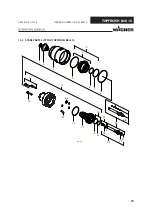
Page 70: ...70 VERSION 01 2018 ORDER NUMBER DOC 2385674 TOPFINISH Bell 1S 15 2 SPARE PARTS LIST FOR TOPFINISH BELL 1S 1 2 3 4 6 7 8 10 5 9 11 12 13 14 15 17 18 19 22 23 B_06676 16 24 20 21 25 26 2K...

Page 71: ...ring set air deflector ring 10 3 2382379 Socket cap screw 11 1 2383264 Screw set 12 1 2382371 O ring 13 1 2372256 Air bearing cartridge 14 1 2382370 O ring 15 1 2382369 O ring 16 1 2383265 O ring set...

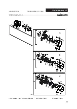
Page 72: ...0 38 27 28 48 31 40 39 B_06874 34 32 41 A 37 29 35 33 36 B C 37 37 41 36 34 33 32 29 35 29 32 35 36 34 41 33 42 43 43 42 42 43 46 44 44 45 45 45 46 46 46 47 47 47 40 39 40 39 38 38 A Valve block 1 pai...

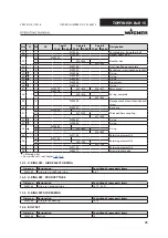
Page 73: ...pin 41 3 2372249 Threaded hose coupling 7 2372249 8 2372249 42 5 2390887 O ring 43 1 2390888 O ring 44 4 2390889 O ring 8 2390889 9 2390889 45 5 2391100 Retaining element D8 46 4 2391103 Retaining el...

Page 74: ...10 EN 14462 2015 EN 1953 2013 EN 13463 1 2009 EN 50176 2009 EN ISO IEC 80079 34 2011 EN ISO 13732 1 2008 Applied national technical standards and specifications in particular DGUV regulation 100 500 C...

Page 75: ...0 PLC BUS HS 2 4 HV PE TOPFINISH RobotBell 1 TOPFINISH Bell 1S HVE 03 01 A2 1 O1 I1 O2 O3 PE HKA 03 02 vio W11 GNYE 6 mm 1x0 75 1 m HKA 02 01 rt W11 B_06628 17 2 HIGH VOLTAGE SYSTEM WITH GROUND SWITCH...

Page 76: ...76...

Page 77: ...77...

Page 78: ...78...

Page 79: ......

Page 80: ...ts liquid wagner group com www wagner group com CERTI F I E D Order no 2385674 Edition 01 2018 Document No 11197700 Version B...

Reviews: