background image


17

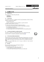
DESCRIPTION

5.1 

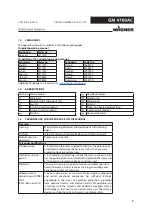
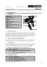
COMPONENTS

Designation

A

J

I

H

K

B
C

E

F

G

D

P_02379

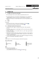
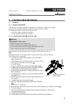
A Suspension hook

B Shaping air regulator
C Spring cap

D Trigger

E Trigger locking device
F Air connection

G Fluid inlet
H Union nut with nozzle protection

I Nozzle / Air cap

J Gun housing

K Turning handle with filter housing

5.2 

MODE OF OPERATION

If the trigger (D) is operated when the trigger locking device (E) is released, then the air 

valve opens first. Atomizing air flows through the air connection (F) to the air cap (I). The 

product valve opens first if approx. 1/2 of the trigger's path is covered. The quantity of air 

for the atomization of the spray jet is preset via the external air automatic controller. The 

spray pattern can be adjusted using the shaping air regulator (B).

5.3 

PROTECTIVE AND MONITORING EQUIPMENT

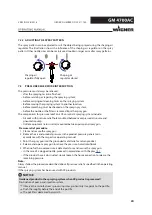
The spray gun is secured with the locking device (E) (the locking device turned in the spraying 

direction and fastened in the groove). The nozzle holder (H) has an anti-contact guard.

5.4 

INCLUDED ITEMS

This AirCoat manual gun is available in two different versions. The choice of nozzle depends 

on the application, therefore this component is not included in the standard scope of 

delivery. A selection guide for spray gun accessories can be found in Chapter 

13

.

5.4.1  VERSION FOR APPLICATION UP TO 25 MPA; 250 BAR; 3625 PSI

Order no. Designation

1

2313585

GM 4700AC 25 MPa, NPSM1/4" product connection

1

2315700

GM 4700AC-H 35 MPa, NPSM1/4" product connection

(H = for processing heated product)

Please always order the nozzle separately.

5.4.2  STANDARD EQUIPMENT

Order no.

Designation

1

2316429

CE Declaration of Conformity

1

2311729

Operating manual, in German

1

see Chapter 

1.3

Operating manual in local language

1

394335

Spring cap 16 MPa; 160 bar; 2320 psi

For special versions the delivery note applies.

VERSION 06/2018

ORDER NUMBER DOC2311730

Summary of Contents for GM 4700AC

Page 1: ...AirCoat Manual Gun for Flat and Round Jet Nozzles Version 06 2018 B_02376...

Page 2: ......

Page 3: ...ctions for the Personnel 12 4 2 1 Personal Safety Equipment 12 4 2 2 Safe Handling of WAGNER Spray Devices 13 4 2 3 Grounding the Unit 13 4 2 4 Product hoses 14 4 2 5 Cleaning and Flushing 15 4 2 6 To...

Page 4: ...eaning Personnel 27 8 1 2 Flushing and Cleaning the Spray Gun 27 8 2 Maintenance 28 8 2 1 Maintenance Personnel 28 8 2 2 Safety instructions 28 8 2 3 Safety Checks and Maintenance Intervals 29 8 2 4 R...

Page 5: ...irCoat Pre atomizer Nozzles AC3000 Plus 45 13 6 Push in Filter 45 13 7 Swivel joints 46 13 8 Hose Sets for GM 4700AC 46 13 9 Hose Sets for GM 4700AC H 46 13 10 Nozzle Extensions 46 13 11 Miscellaneous...

Page 6: ...s in this manual highlight particular dangers to users and to the device and state measures for avoiding the hazard These warning instructions fall into the following categories DANGER Immediate risk...

Page 7: ...roduct pressure generator Pump or pressure tank Personnel qualifications Trained person Is instructed in the tasks assigned to him her the potential risks associated with improper behavior as well as...

Page 8: ...N POTENTIALLY EXPLOSIVE AREAS The device is suitable for use in potentially explosive areas as defined in Directive 2014 34 EU ATEX see Explosion protection marking Chapter 3 1 2 4 PROCESSIBLE WORKING...

Page 9: ...ature can be found in Chapter 5 5 2 Safe Handling of WAGNER Spray Devices Mechanical sparks can form if the device comes into contact with metal In an explosive atmosphere knocking or pushing metal ag...

Page 10: ...131 F Wagner International AG Altstaetten Made in Switzerland B_04161 1 2 3 4 6 5 Designation 1 Serial number 2 Maximum air inlet pressure 3 Maximum product pressure see spring cap 4 Maximum product t...

Page 11: ...m electrical devices 4 1 2 A SAFE WORK ENVIRONMENT Hazard due to dangerous fluids or vapors Severe or fatal injuries due to explosion hazard or inhalation swallowing or contact with the skin or eyes E...

Page 12: ...intained and repaired by trained personnel Refer to the operating instructions for information about the required personnel qualifications 4 2 SAFETY INSTRUCTIONS FOR THE PERSONNEL Always follow the i...

Page 13: ...amination can be suspended until the next start up In the event of skin injuries caused by lacquer or flushing agents Note the lacquer or flushing agent that you have been using Consult a doctor immed...

Page 14: ...nly in suitable places Hoses should not be laid in the following places under any circumstances in high traf c areas on sharp edges on moving parts or on hot surfaces Ensure that the hoses are never r...

Page 15: ...used an explosive mixture may temporarily exist inside the lines and components of equipment Only electrically conductive tanks may be used for cleaning and flushing agents The tanks must be grounded...

Page 16: ...event of work interruptions Relieve the pressure from the spray gun high pressure hoses and all devices Secure the spray gun against actuation Switch off the energy and compressed air supply Disconnec...

Page 17: ...issecuredwiththelockingdevice E thelockingdeviceturnedinthespraying direction and fastened in the groove The nozzle holder H has an anti contact guard 5 4 INCLUDED ITEMS This AirCoat manual gun is ava...

Page 18: ...30 50 100 150 200 Weight g oz 595 g 20 9 oz pH range of the product pH 3 5 9 0 Maximum product temperature C F 55 131 80 176 Maximum air temperature C F 43 109 Sound level at 0 3 MPa 3 bar 43 5 psi a...

Page 19: ...d commissioned 6 2 STORAGE CONDITIONS Until the point of assembly the device must be stored in a dry location free from vibrations and with a minimum of dust The device must be stored in closed rooms...

Page 20: ...M A B C E D F H G J L K M B_02380 N I Designation Designation A Product pump H High pressure product hose B Compressed air shut off valve I High pressure filter product pressure release C Pressure reg...

Page 21: ...and the spray gun are suitable for the pressure generated in the device Ensure that the following information can be seen on the high pressure hose manufacturer permissible operating pressure date of...

Page 22: ...nion nut with nozzle guard and tighten by hand 6 Visually check the permissible pressures for all the system components 7 Make sure that the device and all other conductive parts within the work area...

Page 23: ...evice and pull trigger and at the same time observe how the product is atomizing 3 Set the spray pressure on the product pump to a point where good product atomization is achieved 4 Open the air press...

Page 24: ...ic pump Outlet equipment return valve mounted between pump and spray gun Pressure relief procedure 1 Close and secure the spray gun 2 Relieve the air and product pressure in the product pressure gener...

Page 25: ...ress AirCoat nozzle C out of air cap B by hand and treat with cleaning agent until all remaining paint has been dissolved Assembly 6 Fit AirCoat nozzle C in nozzle seal D 7 Fit air cap B over nozzle C...

Page 26: ...p B onto the spray gun and tighten by hand 8 Switch the product pressure back on 9 Turn the locking device to the spraying position and briefly pull trigger 10 When the blockage has been flushed out s...

Page 27: ...onal safety equipment grounding and all devices ready to use P_02381 Trigger locking device in secured position Air Product 2 Relieve the pressure of the product pressure generator and of the spray gu...

Page 28: ...y WAGNER original spare parts and accessories Only repair and replace parts that are listed in the Spare parts chapter and that are assigned to the unit Before all work on the device and in the event...

Page 29: ...pressure generator and application device is reduced due to environmental influences even when handled correctly Check hoses pipes and couplings every day and replace if necessary Before every commiss...

Page 30: ...wrench Air hose 4 Place the size D open end wrench on the upper part of the air connection and hold it in place 5 Loosen the air hose s nut with a size C open end wrench Assembly 6 Screw on the produc...

Page 31: ...r insert 64 out of the filter housing 67 6 Thoroughly clean all parts with flushing agent Assembly 7 Push the cleaned or new filter insert 64 with opening downwards into the filter housing 67 8 Insert...

Page 32: ...the spray product in accordance with the manufacturer s instructions Nozzle partially clogged Nozzle cleaning 7 4and7 4 2 The drilled holes in the air cap are damaged or clogged Clean or replace the a...

Page 33: ...ork interruptions Relieve the pressure from the spray gun high pressure hoses and all devices Secure the spray gun against actuation Switch off the energy and compressed air supply Disconnect the cont...

Page 34: ...vice 4 Unscrew the spring cap 5 using a size 15 mm 0 59 inch socket wrench and remove the pressure springs 2 and 3 5 Loosen the screw 22 and remove together with the nut 20 6 Remove the trigger 21 7 L...

Page 35: ...eptible when moving the valve rod 34 in the valve tappet Note The seal 52 can be pulled out of the cover 53 with the help of an eye bolt 10 4 2REPLACING THE ROD SEAL 1 Carefully pull the rod seal 35 o...

Page 36: ...n with a size 5 mm 0 20 inch open end wrench tightening torque 5 1 Nm 3 69 lbft Note reference dimension 6 Carefully insert the complete valve rod B into the gun housing 7 Screw in the sealing screw 1...

Page 37: ...verse order 10 6 REPLACING THE AIR SEALING RING NOTICE Shaping air and atomizer air not separate Poor spray pattern Spray jet cannot be adjusted Handle the sealing ring 14 with care 1 Relievethepressu...

Page 38: ...060 E D B C A B_02397 Unscrew the nozzle by hand Note The sealing fitting E can be pulled out of the nozzle body using a small eye wood bolt Nozzle wrench D Order No 128901 Eject with 1 5 mm 0 06 inch...

Page 39: ...y toxic gases Examine the compatibility of the cleaning agents and working media on the basis of the safety data sheets WARNING Hot gun housing Burns Wear protective gloves when dismounting the filter...

Page 40: ...Wear protective gloves when dismounting the filter connection 3 Harden the adhesion point in the housing in an oven at 40 C 104 F for at least 30 minutes 4 After cooling off completely assemble the s...

Page 41: ...the trigger lever locking device into the locking position configure the air product pressure and pull the trigger lever Neither air nor product may leak or escape Check that the trigger lever locking...

Page 42: ...gun or blow out with air Flush the gun without the valve and air cap In doing so you can remove the air connection hose Close the flushing valve When almost no more product comes out remove the produ...

Page 43: ...zle insert R16 16 0 43 430 approx 250 9 84 132726 Nozzle insert R17 17 0 48 480 approx 250 9 84 132727 Nozzle insert R18 18 0 53 530 approx 250 9 84 132728 Nozzle insert R19 19 0 59 590 approx 250 9 8...

Page 44: ...13 413 513 613 813 100 0 013 0 33 0 55 0 145 15 115 215 315 415 515 615 815 0 015 0 38 0 75 0 198 17 217 317 417 517 617 817 60 0 017 0 43 0 96 0 254 19 219 319 419 519 619 819 50 0 019 0 48 1 20 0 31...

Page 45: ...le please select the number from the table and replace the three xxx Example nozzle 410 article number 321410 Spray angle Product filter in mesh Edge filter Gun filter Drilled hole Product flow Spray...

Page 46: ...si Air G1 4 10 m 32 8 ft DN 6 mm ID 0 24 inch 1 MPa 10 bar 145 psi 2309634 AC hose set DN4 PN270 1 4 NPS 15 0 m PA T Product 1 4 NPS 15 m 49 2 ft DN 4 ID 0 16 inch 27 MPa 270 bar 3916 psi Air G1 4 15...

Page 47: ...set GM 4700AC 367560 Double connector NPSM1 4 external thread for product hose extension B_02685 9985720 Double nipple G1 4 external thread for air hose extension B_02686 2324747 Sealing collar UHMW...

Page 48: ...48...

Page 49: ...ded in the warranty terms Included in service set Notice These parts are not covered by warranty terms Not part of standard equipment available however as additional extra Explanation of order no colu...

Page 50: ..._02391 5 4 18 19 10 12 34 50 51 52 25 27 28 22 80 82 21 20 14 15 16 17 13 55 56 57 58 59 60 61 63 62 36 84 24 23 2 3 8 B 69 36 85 64 66 67 83 6 1 26 35 11 86 87 53 88 36 80 29 65 68 5 70 Detail B VERS...

Page 51: ...94601 Trigger 22 1 394319 Screw 23 1 394334 Safety clip 24 1 9935088 Parallel pin 25 1 394313 Air tappet 26 1 9974243 O ring 27 1 394303 Mounting bracket 28 1 9921906 Lock washer 29 1 2324766 Air swiv...

Page 52: ...GM 4700AC complete 69 1 2352651 Spring cap 35 MPa 350 bar 5076 psi 70 1 Pressure spring for spring cap 35 MPa 350 bar 5076 psi 1 394941 Service set GM 4600 4700AC Wearing part Included in service set...

Page 53: ...B_02392 65 4 18 19 10 12 34 50 51 52 25 27 28 22 80 82 21 20 14 15 16 17 13 55 56 57 58 59 60 61 63 62 84 24 23 3 8 B 85 64 66 67 83 6 1 26 35 11 86 87 53 70 69 88 36 36 36 80 29 71 5 72 5 Detail B VE...

Page 54: ...319 Screw 23 1 394334 Safety clip 24 1 9935088 Parallel pin 25 1 394313 Air tappet 26 1 9974243 O ring 27 1 394303 Mounting bracket 28 1 9921906 Lock washer 29 1 2324766 Air swivel complete 34 1 39492...

Page 55: ...4600 4700AC Wearing part Included in service set Not part of the standard equipment but available as a special accessory 15 EU DECLARATION OF CONFORMITY Herewith we declare that the supplied version o...

Page 56: ...ts liquid wagner group com www wagner group com CERTI F I E D Order no 2311730 Edition 06 2018 Document No 11099801 Version H...

Reviews: