MagicSpeed
Connecting the electrical power to MagicSpeed
29
7.2
Laying and connecting the cable
You will find a summary of the wiring in fig.
d
, page 9.
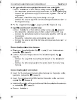
Connecting the wiring harness for the CAN bus
➤
Disconnect the battery.
➤
Pull the plug protector (fig.
6
2, page 5) off the diagnostic plug (fig.
6
2,
page 5).
✓
The wires can now be disconnected with a screwdriver (fig.
6
A,
page 5).
➤
Connect the
blue
wire of the CAN bus wiring harness (fig.
7
, page 5):
– Disconnect the purple/red wire (
1
) from socket 14 of the diagnostic
plug
– Connect the purple/red wire (
1
) to the blue wire (
2
) of the CAN bus
wiring harness
– Protect the connection using an insulating sleeve (
3
)
– Connect the blue wire (
4
) of the CAN bus wiring harness to socket 14
of the diagnostic plug
➤
Connect the
pink
wire of the CAN bus wiring harness (fig.
8
, page 6):
– Disconnect the white/red wire (
1
) from socket 6 of the diagnostic plug
– Connect the white/red wire (
1
) to the pink wire (
2
) of the CAN bus wir-
ing harness
– Protect the connection using an insulating sleeve (
3
)
– Connect the pink wire (
4
) of the CAN wiring harness to socket 6 of the
diagnostic plug
No.
Component
No.
Component
1
Electronic module
5
Main wiring harness con-
nection
2
Diagnostic plug
6
CAN bus connection
3
Main wiring harness
7
Control element connection
4
Vehicle CAN bus wire
8
ESP switch
_MS-902.book Seite 29 Montag, 28. Februar 2011 3:47 15
Summary of Contents for MagicSpeed MS900
Page 3: ...MagicSpeed 3 1 2 3 4 6 8 5 7 9 1 2 3...
Page 4: ...MagicSpeed 4 2 1 4 1 5...
Page 5: ...MagicSpeed 5 2 1 A 6 1 pu rt bl 2 3 4 7...
Page 6: ...MagicSpeed 6 1 2 3 4 pk ws rt 8 1 2 3 4 rt ge rt 9...
Page 7: ...MagicSpeed 7 1 0 1 2 3 4 rt ge rt Opel 2008 a...
Page 8: ...MagicSpeed 8 1 2 b 1 2 3 c...


