


EN
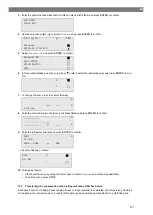
17.
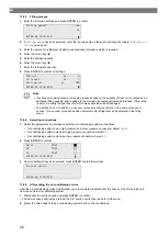
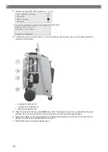
Use the cursor keys or to select whether to flush the entire air conditioning system or just individual com-
ponents:
Full flushing
Fast flushing
ENTER-OK STOP-EXIT
18.
Press
ENTER
to confirm.
19.
Follow the instructions in the display.
After flushing is completed, the basic menu for the A/C service unit appears.
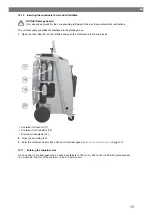
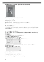
20.
If necessary, remove the adapter from the flushing circuit and reconnect all the components to the refrigerant
circuit. Fit the connections of the A/C service unit to the vehicle air conditioning system and open them.
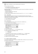
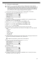
21.
In the basic menu use the cursor keys or to select
Free selection
.
Short selection
Free selection
Other selections
ENTER-OK
22.
Press
ENTER
to confirm.
23.
If necessary, use the keypad to enter the data and press
ENTER
to confirm. If no data has to be entered,
press
ENTER
to switch to the next program step.
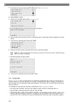
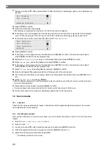
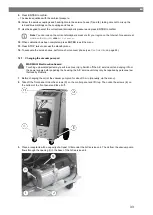
24.
Deselect
Rec/Recycling phase
using
No
(the setting flashes) and press
ENTER
to confirm.
25.
Select
Vacuum phase
(the setting flashes) and press
ENTER
to confirm.
26.
If necessary, use the keypad to enter the data and press
ENTER
to confirm. If no data has to be entered,
press
ENTER
to switch to the next program step.
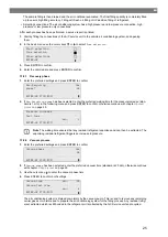
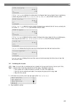
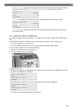
27.
Select
Filling phase
(the setting flashes) and press
ENTER
to confirm.
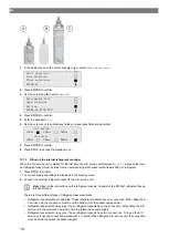
28.
Enter the refrigerant filling quantity (note the oil filling quantity of the compressor).
29.
Then follow the instructions on the display: Select the setting (which then flashes) and press
ENTER
to con-
firm.
30.
Select
Process start
by pressing
ENTER
.
After the filling is complete, you will be prompted to disconnect the hoses of the A/C service unit from the vehi-
cle air conditioning system.
31.
Disconnect the service hoses and press
ENTER
to confirm.
The service hoses will now be drained. the A/C service unit is then ready for further use.
32.
Put the valve caps of the vehicle air conditioning system back on the connections.
14 Service tasks
14.1 Leak test
Check the A/C service semiannual for leaks in accordance with the applicable legal requirements. Use an elec-
tronic leak detector for this purpose.
14.2 Resetting the counters
After you have finished one or more service tasks, you must reset the respective counters. To do this proceed as
follows:
1.
Enter the
Other selections
–
Service
menu.
2.
Enter the code
7782
.
3.
Use the cursor keys or to select the required entry and press
ENTER
to confirm.
4.
Follow the display instructions, and press and hold the
ENTER
button for 3
s.
5.
Switch back to the previous selection using
STOP
.
The following counters can be reset:
28
Summary of Contents for ASC 6300 G
Page 9: ...EN 16 USB port 9...
Page 41: ...EN 17 1 Flowchart ASC6300 G Legend 41...
Page 44: ...EN 17 2 Flowchart ASC6400 G Legend 44...
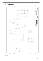
Page 47: ...EN 17 3 Circuit diagram ASC6300 G 47...
Page 48: ...EN 48...
Page 49: ...EN 17 4 Circuit diagram ASC6400 G 49...
Page 50: ...EN 50...
Page 58: ...FR 16 Port USB 58...
Page 92: ...FR 17 1 Organigramme ASC6300 G L gende 92...
Page 95: ...FR 17 2 Organigramme ASC6400 G L gende 95...
Page 98: ...FR 17 3 Sch ma lectrique ASC6300 G 98...
Page 99: ...FR 99...
Page 100: ...FR 17 4 Sch ma lectrique ASC6400 G 100...
Page 101: ...FR 101...
Page 109: ...DE 16 USB Anschluss 109...
Page 142: ...DE 17 1 Flussdiagramm ASC6300 G Legende 142...
Page 145: ...DE 17 2 Flussdiagramm ASC6400 G Legende 145...
Page 148: ...DE 17 3 Schaltplan ASC6300 G 148...
Page 149: ...DE 149...
Page 150: ...DE 17 4 Schaltplan ASC6400 G 150...
Page 151: ...DE 151...
Page 153: ...RU 4 Tel 49 0 2572 879 0 5 6 Domestic 153...
Page 154: ...RU 6 1 154...
Page 155: ...RU 6 2 R1234yf 405 C R134a 743 C R153A 6 3 155...
Page 157: ...RU Dometic 10 10 1 230 240 50 60 190 10 2 10 3 10 4 157...
Page 158: ...RU 11 1 2 3 4 ECO 5 6 7 8 9 10 11 12 13 14 15 158...
Page 159: ...RU 16 USB 159...
Page 182: ...RU 11 12 ENTER 13 14 15 D 16 E 17 15 18 19 20 R1234yf 179 21 179 14 5 12 182...
Page 184: ...RU 2 D E 3 I 4 G 5 J 6 J 7 H G 8 9 10 179 184...
Page 188: ...RU 181 ENTER 3 183 ENTER 3 01 02 03 04 188...
Page 189: ...RU 09 10 12 52 USB USB USB FAT32 60 61 G1 00001 00002 00003 00004 10 C 45 C 00001 189...
Page 192: ...RU 17 1 ASC6300 G 192...
Page 194: ...RU X23 DO X3 UV X4 X5 Z2 X6 Z2 X7 HP X8 HP X9 RE 194...
Page 195: ...RU 17 2 ASC6400 G 195...
Page 197: ...RU X10 VC X16 CY X2 LP X23 DO X3 UV X4 X5 Z2 X6 Z2 X7 HP X8 HP X9 RE 197...
Page 198: ...RU 17 3 ASC6300 G 198...
Page 199: ...RU 199...
Page 200: ...RU 17 4 ASC6400 G 200...
Page 201: ...RU 201...
Page 209: ...ES 16 Conexi n USB 209...
Page 244: ...ES 17 1 Diagrama de flujo ASC6300 G Leyenda 244...
Page 247: ...ES 17 2 Diagrama de flujo ASC6400 G Leyenda 247...
Page 250: ...ES 17 3 Esquema de conexiones ASC6300 G 250...
Page 251: ...ES 251...
Page 252: ...ES 17 4 Esquema de conexiones ASC6400 G 252...
Page 253: ...ES 253...
Page 254: ...4445103554 2022 11 30...


