


Maintenance
WP 1235A
wpm_tx001427gb.fm
24
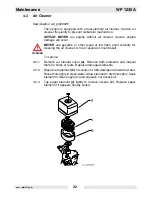
4.6
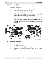
Carburetor Adjustment
See Graphic: wc_gr000032
4.6.1
Start the engine and allow it to warm up to operating temperature.
4.6.2
Set the pilot screw
(a)
two turns out. See
Note
.
4.6.3
With the engine idling, turn the pilot screw
(a)
in or out to the setting
that produces the highest rpm.
4.6.4
After the pilot screw is adjusted, turn the throttle stop screw
(b)
to
obtain the standard idle speed.
See
Technical Data
.
Note:
On some engines the pilot screw is fitted with a limiter cap
(c)
to prevent excessive enrichment of the air-fuel mixture in order to
comply with emission regulations. The mixture is set at the factory and
no adjustment should be necessary. Do not attempt to remove the
limiter cap. The limiter cap cannot be removed without breaking the
pilot screw.
4.7
Cleaning Sediment Cup
See Graphic: wc_gr000029
4.7.1
Turn the fuel valve off.
4.7.2
Remove the sediment cup
(a)
and the O-ring
(b)
.
4.7.3
Wash both thoroughly in a nonflammable solvent. Dry and reinstall
them.
4.7.4
Turn the fuel valve on and check for leaks.
wc_gr000032
Summary of Contents for WP 1235A
Page 1: ...Operator s Manual Vibroplate WP 1235A 0402343en 001 0110 0 4 0 2 3 4 3 E N ...
Page 11: ...WP 1235A Safety Information wpm_si000445gb fm 9 1 5 Label Locations wpmgr007303 ...
Page 32: ......
Page 34: ......
Page 36: ......
Page 38: ......