


BA EZ17 en* 1.1 * ez17b510.fm
5-15
Operation 5
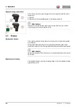
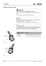
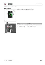
Hydraulic swivel unit brake:
Normal braking: release the control lever.
Maximum braking: press the control lever in the opposite direction until the
upper carriage is at a standstill.
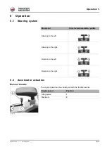
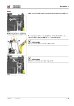
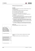
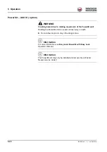
ISO/SAE controls (option)
The standard equipment of the machine includes ISO controls. SAE
controls are available as an option. This results in a different control lever
operation
WARNING
Accident hazard due to modified control mode!
Modified controls can cause incorrect operation, and serious injury or
death.
►
Before starting work, check the selected control type.
►
Always secure the wing nut on the reversing valve.
►
Do not operate the machine with a defective wing nut. Contact a
Wacker Neuson service center.
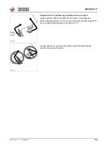
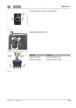
The reversing valve is located at the left under the operator’s seat.
Fig. 89
A
B
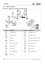
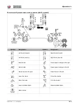
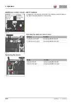
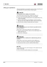
Wiring diagram
Controls
A
ISO controls
B
SAE controls
Summary of Contents for E13-01
Page 6: ...EG 2 BA EZ17 en 1 1 ez17konf fm Declaration of conformity Notes...
Page 36: ...2 22 BA EZ17 en 1 1 Safety_01_0 fm 2 Safety Notes...
Page 45: ...BA EZ17 en 1 1 ez17e300 fm 3 9 Introduction 3 Warning labels...
Page 50: ...3 14 BA EZ17 en 1 1 ez17e300 fm 3 Introduction Labels...
Page 90: ...4 36 BA EZ17 en 1 1 ez17i400 fm 4 Putting into operation Notes...
Page 158: ...5 68 BA EZ17 en 1 1 ez17b510 fm 5 Operation Notes...
Page 216: ...7 50 BA EZ17 en 1 1 ez17w710 fm 7 Maintenance Notes...
Page 220: ...8 4 BA EZ17 en 1 1 ez17b800 fm 8 Malfunctions Notes...
Page 244: ...9 24 BA EZ17 en 1 1 ez17t900 fm 9 Technical data Dimensions Fig 243...
Page 246: ...9 26 BA EZ17 en 1 1 ez17t900 fm 9 Technical data Notes...