background image

3-8

SHB 803 en – Edition 2.4 * 803s311.fm


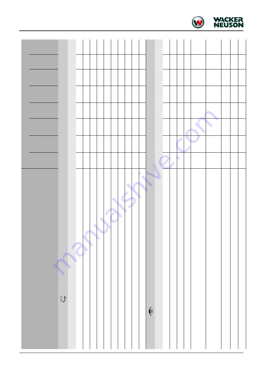
Maintenance

3.3

M

ain

tenan

ce plan (

overview)

Work description

For servicing and maintenance on the attachment, p

lease refer to the ope

ration and maintenance manual of 

the attachment manufacturer.

Maint

enan

ce plan/o

perat

ing

 ho

urs (

o/h

)

Maintenance

(once a day)

Every 50 o/h

Every 250 o/h

Every 500 o/h

Every 1000 o/h

once a year

Every 2000 o/h

Customer

Authorized

service center

Fluid and filter changes (

):

Perform the following oil and filter changes

 (check oil leve

ls after test run):

Engine oil 

1

●●

Engine oil filter 

2

●●

Fuel filter 

3

●●

W

ater separator

●●

C

oolant

●●

H

ydr

aulic

 oi

l fil

ter ins

ert 

4

●●

H

ydr

aulic

 oi

l

5

●●

D

rain condensation water from the hyd

raul

ic oil reservoir (fro

m se

rial no

. A

H

02272)

●●

Air filter ele

m

ent (up to

 seria

l no. AI00875)

●●

Air filter ele

m

ent according to di

rt indicator (from serial no. AI00876) 

6


●●

Inspection work (

):

Check the following materi

al. Refill if necessary:

Engine oil

●●

Engine coolant

●●

Fuel

●●

H

ydr

aulic

 oi

l

●●

Check the function of the

 pedals (up to serial n

o. A

I00975)

C

lean, lubricate or repair the pedals

●●

Check the function of the

 pedals, they must flip back automatically (from serial no. AI00976)

C

lean, lubricate or repair the 

pedals, check the torsion springs

●●

Clean water ducts 

7

●●

Check radiator for engine and hydraulic

 oil for dirt. Clean if necessary 

●●

Check cooling systems and hoses for 

leaks an

d pressure (visual check)

●●

Mainte

nanc

e

Summary of Contents for 803 Dualpower

Page 1: ...Service Manual Track excavator Machine model 803 Edition 2 4 Order no 1000164843 Language en ...

Page 2: ... regulations in particular of the copyright protection shall be subject to civil and criminal prosecution Wacker Neuson Linz GmbH keep abreast of the latest technical developments and constantly improve their products For this rea son we may from time to time need to make changes to figures and descriptions in this documentation which do not reflect products that have already been delivered and th...

Page 3: ...trim 2 6 Relays behind the right hand trim 2 7 Fuses and relays with Dual Power option 2 7 Noise levels 2 8 Vibration 2 8 Coolant compound table 2 8 Model specific tightening torques 2 9 General tightening torques 2 9 Tightening torques for hydraulic threaded fittings dry assembly 2 9 Tightening torques for high resistance threaded fittings 2 11 Dimensions model 803 up to serial no AI00966 2 12 Di...

Page 4: ...36 Checking the hydraulic oil level 3 36 Adding hydraulic oil 3 38 Changing hydraulic oil 3 39 Replacing the filter cartridge 3 39 Checking hydraulic pressure lines 3 40 Tracks 3 41 Checking track tension 3 41 Setting the tracks 3 42 Lubrication points on boom up to serial number AI00966 3 43 Lubrication strip 3 44 Overview of lubrication points from serial no AI00967 3 45 Parking the machine 3 46...

Page 5: ...ouble 4 13 Overview of engine 3TNV74F SNNS Tier IV final from 2012 4 15 Fuel system 4 17 Cooling system 4 18 Altitude dependent output reduction 4 19 Checking and adjusting valve clearance 4 20 Tightening order for cylinder head bolts 4 22 Order for removing the cylinder head bolts 4 22 Order for installing the cylinder head bolts 4 22 Checking the injection nozzles 4 23 Pressure check 4 23 Checki...

Page 6: ... levers up to serial no AI00814 5 18 Control levers from serial number AI00815 5 19 Drive levers from serial number AI00815 5 20 Lock lever from serial number AI00815 5 21 Troubleshooting in the hydraulic system 5 22 Plastic trims 5 22 Hydraulics diagram legend 5 24 Hydraulics diagram 5 25 Hydraulics diagram Dual Power option 5 26 Main valve block diagram 5 27 Electrical system Ohm s Law current v...

Page 7: ...15 Horn wiring harness 6 16 Battery lead 6 17 Indicating instrument wiring harness Dual Power option 6 18 Engine chassis wiring harness Dual Power option 6 19 Seat console wiring harness 6 20 Wiring diagram 6 22 Wiring diagram Tier IV Yanmar 6 23 Wiring diagram Dual Power option 6 24 Options Rollbar 7 2 TOPS rollbar up to serial number AF01416 7 2 Lowerable ROPS rollbar from serial no AF01417 to s...

Page 8: ...I 6 SHB 803 en Edition 2 4 803s20IVZ fm Table of contents ...

Page 9: ...Operation ...

Page 10: ...f your machine and maintains its value We reserve the right to improve the technical standard of our machines without adapting the service manual Modifying Wacker Neuson products and fitting them with additional equipment and attachments not included in our delivery program requires Wacker Neuson s written authorization otherwise warranty and product liability for possible damage caused by these m...

Page 11: ... the operator or other persons Measures for avoiding danger Caution Failure to observe the instructions identified by this symbol can cause damage to the machine Measures for avoiding danger for the machine Notice This symbol identifies instructions for a more efficient and economical use of the machine Environment Failure to observe the instructions identified by this symbol can cause damage to t...

Page 12: ...hority and by using spare parts equipment attachments and optional equipment that have not been checked and released by Wacker Neuson Wacker Neuson will not be liable for damage resulting from this Wacker Neuson Linz GmbH shall not be liable for personal injury and or damage to property caused by failure to observe the safety instructions and the Operator s Manual and by the negligence of the duty...

Page 13: ...w is located on the cylinder head cover engine Hydraulic pump type label The type label arrow is located on the hydraulic pump housing Main valve block type label The type label arrow is located on the lower side of the main valve block Traveling drive type label The type label arrow is located on the traveling drive Fig 1 Type label symbolic representation Fig 2 Diesel engine type label Fig 3 Hyd...

Page 14: ...1 6 SHB 803 en Edition 2 4 803s110 fm Operation Swivel unit type label The type label arrow is located on the swivel unit Fig 6 Swivel unit type label ...

Page 15: ...966 Fig 7 Machine outside views 1 Boom light 2 Boom 3 Stick 4 Track 5 Travel gear 6 Stabilizer blade 7 Handhold 8 Lifting eye for loading tying down the machine 9 Engine cover 10 Storage bin for Operator s Manual 11 Lock lever 12 Track tensioner 1 2 7 3 9 8 6 5 4 8 2 4 5 6 8 7 11 10 12 12 3 ...

Page 16: ... Fig 8 Machine outside views 1 Boom light 2 Boom 3 Stick 4 Track 5 Travel gear 6 Stabilizer blade 7 Handhold 8 Lifting eye for loading tying down the machine 9 Engine cover 10 Storage bin for Operator s Manual 11 Lock lever 12 Track tensioner 13 ROPS rollbar option 14 Shatter protection option 8 4 5 6 10 11 14 7 2 3 8 12 ...

Page 17: ...l no AI00814 1 3 9 8 2 7 6 4 5 Pos Designation 1 Operator seat 2 Upper carriage lock 3 Engine cover lock 4 Preheating start switch 5 Stabilizer blade telescopic undercarriage lever 6 Stabilizer blade telescopic travel gear changeover lever 7 Auxiliary hydraulics 8 Engine cover 9 Handhold ...

Page 18: ...Operation 10 11 12 13 14 15 17 16 18 Pos Designation 10 Boom swivel auxiliary hydraulics pedal 11 Footrest 12 Control lever lock 13 Throttle 14 Control lever left 15 Drive lever left 16 Drive lever right 17 Control lever right 18 Indicators ...

Page 19: ...copic travel gear lever 6 Stabilizer blade telescopic travel gear changeover lever 7 Boom swivel pedal 8 Engine cover 9 Handhold 10 Auxiliary hydraulics pedal 11 Footrest 12 Lock lever 13 Throttle 14 Control lever left 15 Drive lever left 16 Drive lever right 17 Control lever right 18 Display element 19 Lever for switching over hammer grab operation option 4 6 1 2 3 5 7 8 10 11 11 12 13 14 15 16 1...

Page 20: ...n 1 9 Display elements overview 22 20 24 21 23 Pos Designation 20 Indicator light red alternator charge function 21 Indicator light red engine oil pressure 22 Indicator light red coolant temperature 23 Indicator light yellow fuel gage 24 Hour meter ...

Page 21: ...peration 1 10 Engine compartment overview up to serial no AI00814 Pos Designation 25 Air filter 26 Throttle cable 27 Fuel filter 28 Swivel unit 29 Thermostat 30 Filler neck 31 Coolant filler inlet 32 Coolant reservoir 29 31 30 25 27 26 32 28 ...

Page 22: ...Operation 1 11 Engine compartment overview from serial no AI00815 37 39 38 33 34 35 40 36 Pos Designation 33 Air filter 34 Fuel filter 35 Throttle cable 36 Swivel unit 37 Thermostat 38 Filler neck 39 Coolant filler inlet 40 Coolant reservoir ...

Page 23: ...Technical data ...

Page 24: ...at 2100 rpm Max torque 51 5 Nm 38 ft lbs at 1500 rpm Max engine speed without load 2270 25 rpm Idling speed 1300 25 rpm Valve clearance intake outlet 0 15 0 25 mm 0 006 0 01 cold Compression 32 4 1 bar 469 9 15 psi at 250 rpm Engine oil pressure 2 9 4 4 bar 42 64 psi at rated output Pressure switch for engine oil pump 0 5 0 1 bar 7 25 1 45 psi Thermostat opening temperature 69 5 72 5 C 157 163 F T...

Page 25: ...pm 39 ft lbs 1800 rpm Max engine speed without load 2675 25 rpm 2 675 25 rpm Idling speed 1300 25 rpm 1 300 25 rpm Valve clearance intake outlet 0 15 0 25 mm 0 006 0 01 cold Compression 32 4 1 bar 469 9 15 psi at 250 rpm Engine oil pressure 3 4 5 bar 43 5 65 3 psi at rated output Pressure switch for engine oil pump 0 5 0 1 bar 7 25 1 45 psi Thermostat opening temperature 71 C 160 F Thermal switch ...

Page 26: ...Connecting rod bearing screw1 22 6 27 5 Nm M7x1 0 16 6 20 3 ft lbs Main bearing screw 75 5 81 5 Nm M10x1 25 55 7 60 ft lbs Flywheel screw 80 4 86 4 Nm M10x1 25 59 3 63 7 ft lbs Hydraulics Model 803 Pump Tier IV final up to 2012 Twin gear pump 2 x 5 cm 2 x 0 3 in rev Flow rate Tier IV final up to 2012 2 x 11 35 l min at 2270 rpm 2 x 3 gal min at 2270 rpm Pump Tier IV final from 2012 Twin gear pump ...

Page 27: ... 8 19 7 5 2 140 2030 5 18 5 4 8 160 2320 6 10 5 2 7 168 2436 6 5 1 3 Travel gear swivel unit Model 803 Travel speeds 1 82 kph 1 13 mph Hill climbing ability no longer than 3 minutes 30 58 Track width 180 mm 7 09 No of track rollers on either side 2 Ground clearance 132 mm 5 2 Ground pressure 0 24 kg cm 3 4 psi Upper carriage swivel speed 8 rpm Stabilizer blade Model 803 Width folded in out 700 860...

Page 28: ... F3 Fig 9 Fuses up to serial number WNCE0801CPAL0050 Fuse no Rated current A Protected circuit F1 40 A Main fuse air pressure sensor output adaptation Yanmar 3TNV74F SNNS F2 10 A Fuse relay indicator cutoff solenoid F3 10 A Fuse horn working light 12 V power outlet up to serial number WNCE0801CPAL0050 travel signal option F4 10 A 12 V power outlet from serial number WNCE0801TPAL0051 F1 F2 F3 Fig 1...

Page 29: ... Fuses and relays with Dual Power option F1 F4 F2 F3 K7 K9 Fuse no Rated current A Protected circuit F1 40 A Main fuse air pressure sensor output adaptation Yanmar 3TNV74F SNNS F2 10 A Fuse relay indicator cutoff solenoid F3 10 A Fuse horn working light 12 V power outlet up to serial number WNCE0801CPAL0050 travel signal option battery control Dual Power option F4 10 A 12 V power outlet from seria...

Page 30: ...nd power level Model 803 Sound power level LWA 1 1 ISO 6395 EC Directives 2000 14 EC and 2005 88 EC 93 dB A Operator perceived sound pressure level LPA 2 2 EN ISO 4871 EC Directives 2000 14 EC and 2005 88 EC 77 dB A Uncertainty KPA 3 3 ISO 6394 EC Directives 84 532 EEC 89 514 EEC 95 27 EEC 1 2 dB A Vibration Effective acceleration value for the upper extremities of the body hand arm vibration Trig...

Page 31: ... Angled engine bracket M10 8 8 45 33 2 Engine bearing M10 8 8 45 33 2 Pump base M10 8 8 45 33 2 Pump M10 8 8 45 33 2 Swivel joint M10 10 9 64 47 2 Bumper M14 12 9 230 169 6 Metric hose fittings for hydraulic applications light execution DKOL Nominal Ø Outer Ø Thread Wrench size Torque Nm ft lbs 05 6L M12X1 5 WS 14 15 11 06 8L M14X1 5 WS 17 20 14 7 08 10L M16X1 5 WS 19 40 29 5 10 12L M18X1 5 WS 22 ...

Page 32: ...3 4A 90 66 180 133 100 74 140 103 26 44 1 04 G1A 150 111 310 229 160 118 190 140 33 25 1 31 G1 1 4A 240 177 450 332 210 155 360 266 41 91 1 65 G1 1 2A 290 214 540 398 260 192 540 398 47 80 1 88 Threaded fittings with various seals for hydraulic applications heavy execution Thread Straight pipe fitting with thread and screwed plug Non return valve with elastic seal Identification aid outside Ø Seal...

Page 33: ...14 135 100 180 133 230 170 110 81 160 118 M16 210 155 275 203 350 258 170 125 250 184 M18 280 207 410 302 480 354 245 181 345 254 M20 410 302 570 420 690 509 340 251 490 361 M22 550 406 780 575 930 686 460 339 660 487 M24 710 524 1000 738 1190 878 590 435 840 620 M27 1040 767 1480 1092 1770 1305 870 642 1250 922 M30 1420 1047 2010 1482 2400 1770 1200 885 1700 1254 With fine pitch thread Thread Scr...

Page 34: ...ed in out 700 860 mm 2 4 2 10 Transport length 2747 mm 9 Max digging depth 1731 mm 5 8 Stick length 890 mm 2 11 Max vertical digging depth 1349 mm 4 5 Max digging height 2863 mm 9 5 Max tilt out height 2035 mm 6 8 Max digging radius 3074 mm 10 1 Max reach at ground level 3028 mm 9 11 Max breakout force at bucket tooth 8 99 kN 2021 lbf Max tearout force 4 51 kN 1014 lbf Min tail end slewing radius ...

Page 35: ...ngth 2747 mm 9 Max digging depth 1766 mm 5 10 Stick length 890 mm 2 11 Max vertical digging depth 1320 mm 4 4 Max digging height 2853 mm 9 4 Max tilt out height 2008 mm 6 7 Max digging radius 3092 mm 10 2 Max reach at ground level 3046 mm 10 Max breakout force at bucket tooth 8 99 kN 2021 lbf Max tearout force 4 51 kN 1014 lbf Min tail end slewing radius 747 mm 2 5 Max tail end lateral projection ...

Page 36: ... 4 4 Max digging height 2853 mm 9 4 Max tilt out height 2008 mm 6 7 Max digging radius 3090 mm 10 2 Max reach at ground level 3046 mm 10 Max breakout force at bucket tooth 8 99 kN 2021 lbf Max tearout force 4 51 kN 1014 lbf Min tail end slewing radius 747 mm 2 5 Max tail end lateral projection 90 rotation of upper carriage Retracted extended telescopic travel gear Stabilizer blade folded in out 39...

Page 37: ...15 Technical data 2 15 Lift capacity table 803 RD Refer to the Operator s Manual of the machine for specific data 2 16 Kinematics E Pin diameter 25 mm 0 98 F Stick width 100 mm 3 9 L Pin distance from bucket mount 165 mm 6 5 Bucket Stick ...

Page 38: ...2 16 SHB 803 en Edition 2 4 803s210 fm Technical data ...

Page 39: ...Maintenance ...

Page 40: ...oil6 6 Hydraulic ester oils HEES PANOLIN HLP Synth 46 BP BIOHYD SE 46 Grease Roller and friction bearings KPF2N 207 7 KP2N 20 according to DIN 51502 EP multipurpose calcium sulphonate complex grease Year round As required Live ring gears Live ring ball bearing race Grease zerks Battery terminals Acid proof grease8 8 Standard acid proof grease FINA Marson L2 Year round As required Fuel tank Diesel ...

Page 41: ... Please refer to the maintenance plan on page 3 8 for additional maintenance Engine oil grade Ambient temperature C F C 20 15 10 5 0 5 10 15 20 25 30 35 40 SAE 10W SAE 20W SAE 10W 30 API CG 4 CH 4 CI 4 ACEA E3 E4 E5 SAE 10W 40 SAE 15W 40 SAE 20 SAE 30 SAE 40 F 4 5 14 23 32 41 50 59 68 77 86 95 104 Application Hydraulic oil Hydraulic oil filter insert Normal work excavation work Replace the first t...

Page 42: ...grades for the hydraulic system depending on temperature Hydrau lics oil grade Ambient temperature C F HVLP1 C 20 15 10 5 0 5 10 15 20 25 30 35 40 50 ISO VG32 ISO VG46 ISO VG68 F 4 5 14 23 32 41 50 59 68 77 86 95 104 122 1 According to DIN 51524 section 3 ...

Page 43: ...clean the fuel prefilter Radiator Check the coolant level Radiator Drain and add new coolant Engine Check valve clearance Adjust if necessary Engine Check the engine oil level Engine Change the engine oil Engine Replace the oil filter Engine Check the V belt tension Travel gear Check track tension Hydraulic system Check oil level Hydraulic system Change the hydraulic oil Hydraulic system Replace t...

Page 44: ...3 6 SHB 803 en Edition 2 4 803s310 fm Maintenance Maintenance label up to serial number AF02412 ...

Page 45: ...SHB 803 en Edition 2 4 803s310 fm 3 7 Maintenance Maintenance label from serial number AF02413 ...

Page 46: ...olant Hydraulic oil filter insert 4 Hydraulic oil 5 Drain condensation water from the hydraulic oil reservoir from serial no AH02272 Air filter element up to serial no AI00875 Air filter element according to dirt indicator from serial no AI00876 6 Inspection work Check the following material Refill if necessary Engine oil Engine coolant Fuel Hydraulic oil Check the function of the pedals up to ser...

Page 47: ...er and electric connections bearing play and function Check preheating system and electric connections Pressure check of primary pressure limiting valves 10 Check tracks for cracks and cuts Check track tension Retighten if necessary Check bearing play of tread rollers track carrier rollers front idlers Check piston rods for damage Check the threaded fittings of the safety devices for example rollb...

Page 48: ...intenance label on page 3 5 Stabilizer blade Swiveling console Swiveling cylinder Boom Stick Attachments Teeth of live ring Live ring ball bearing Ball sockets ISO SAE changeover option Functional check Check the function of the following assemblies components Rectify if necessary Lights and acoustic warning system Check pedal function 3 3 Maintenance plan overview Work description For servicing a...

Page 49: ...o the dirt indicator every 1000 o h or once a year at the latest Replace after 50 o h when in extensive use in environments with acidic air such as acid production facilities steel and aluminum mills chemical plants and other nonferrous metal plants 7 Clean the water ducts every other 1000 o h servicing 8 Clean and adjust the fuel injection pump every other 1000 o h servicing 9 Check and adjust in...

Page 50: ... When using compressed air dirt and debris can be blown into your face Therefore wear safety glasses protective masks and clothing when using compressed air 3 6 Safety relevant parts Daily servicing and maintenance and maintenance according to maintenance plan A must be performed by a specifically trained person All other maintenance must be per formed by trained and qualified personnel only The f...

Page 51: ...he left in travel direction Danger All work involving fuel carries an increased Fire and poisoning hazard Do not refuel in closed rooms Never perform work on the fuel system near open flames or sparks Environment Use a suitable container to collect the fuel as it drains and dispose of it in an environmentally friendly manner Notice Do not run the fuel tank completely dry Otherwise air is drawn int...

Page 52: ...e fig 2 Barrels must neither be rolled nor tilted before refueling Protect the suction pipe opening of the barrel pump with a fine mesh screen Immerse it down to a max 150 mm 5 9 in above the bottom of the barrel Only fill the tank using refueling aids funnels or filler pipes with integral microfilter Keep all refueling containers clean at all times Diesel fuel specification Use only high grade fu...

Page 53: ...after starting the engine Let the fuel system run by performing a test run of 5 minutes at idling speed If the engine runs smoothly for a while and then stops or if it does not run smoothly Stop the engine Raise the lock lever Remove the starting key Bleed the fuel system again as described above Have this checked by authorized personnel if necessary Fuel prefilter with water separator Check the f...

Page 54: ...6 SHB 803 en Edition 2 4 803s312 fm Maintenance Environment Thread A is fitted with a hose Collect the water as it drains with a suitable con tainer and dispose of it in an environmentally friendly manner ...

Page 55: ...entally friendly manner Open the engine cover Close stop cock B horizontal Unscrew the union nut Remove the transparent housing Remove the old filter insert Put the new filter insert in place Fit the housing back on again apply a thin coat of oil or diesel fuel to the sealing surface Open stop cock B vertical Bleed the fuel system see chapter Bleeding the fuel system on page 3 15 Check the filter ...

Page 56: ...gine After stopping a warm engine wait at least 5 minutes before checking Park the machine on level ground Stop the engine Raise the lock lever Remove the starting key Let the engine cool down Open the engine cover Clean the area around the oil dipstick with a lint free cloth Pull out oil dipstick A Wipe it with a lint free cloth Push it back in as far as possible Withdraw it and read off the oil ...

Page 57: ...ngine oil too fast via filler inlet B in the cylinder head cover can cause engine damage Add the engine oil slowly so it can go down without entering the intake system Clean the area around oil filler cap B with a lint free cloth Open filler cap B Pull out oil dipstick A and wipe it with a lint free cloth Add engine oil Wait about 3 minutes until all the oil has run into the oil sump Check the oil...

Page 58: ...g operating temperature oil temperature about 80 C Stop the engine Place a container under the opening to collect the oil as it drains Unscrew the oil drain plug Completely drain the oil Add engine oil see chapter Adding engine oil on page 3 19 Screw the oil drain plug back on again Start the engine and let it run briefly at low speed Stop the engine Wait a moment until all the oil has run into th...

Page 59: ...re that the thread adapter is correctly placed in the filter head Clean the filter head inside with a lint free cloth Apply a thin coat of fresh engine oil to rubber seal B of the new oil filter cartridge Tighten the new filter cartridge by hand until the gasket makes contact Tighten oil filter cartridge A by hand by about a further half revolution Ensure that the oil level is correct Let the engi...

Page 60: ... the maintenance plans in the appendix for the intervals If coolant must be added frequently check the cooling system for leaks and or con tact your dealer Never add cold water coolant if the engine is warm After filling the coolant reservoir make a test run with the engine and check the cool ant level again after stopping the engine The use of the wrong coolant can destroy the engine and the radi...

Page 61: ...d eye contact with coolant If coolant comes into contact with the eyes Immediately rinse with clean water and seek medical assistance Notice Do not add a different coolant to the one in the reservoir Only use the coolant prescribed by Wacker Neuson see Fluids and lubricants on page 3 2 Checking the coolant level Park the machine on level ground Stop the engine Raise the control lever base Remove t...

Page 62: ...voir Start the engine and let it warm up for about 5 10 minutes Stop the engine Remove the key and carry it with you Let the engine cool down Check the coolant level again The coolant level must be above the sheet metal bracket of the coolant reservoir If necessary add coolant and repeat the procedure until the coolant level remains constant Close and lock the engine cover Caution Do not add a dif...

Page 63: ...olant prescribed by Wacker Neuson see Fluids and lubricants on page 3 2 After the engine has cooled down Release overpressure in the radiator Open the cap to the first notch and fully release the pressure Open filler cap 14 B Remove the left hand articulation screw of the rollbar option Remove screws S Remove the casting and the rollbar element option Open the drain plug on the lower side of the r...

Page 64: ...s present for example in acid production facilities steel and aluminum mills chemical plants and other nonferrous metal plants Replace air filter element B after 50 operating hours at the latest General instructions for maintenance of the air filter element Store air filter elements in their original packaging and in a dry place Do not knock the air filter element against other objects as you inst...

Page 65: ...ll intact air filter elements Carefully insert a new air filter element B in housing section F Position housing section E ensure that it is properly seated Close bow clips D Notice Ensure that dust valve G shows downward once it is installed 3 11 Air filter from serial no AI00876 Caution The air filter element will be damaged if it is washed or brushed out Bear in mind the following to avoid prema...

Page 66: ...ze the discharge slot of dust valve D Clean the discharge slot if necessary Replacing air filter elements Replace the outside air filter element B as follows Stop the engine Raise the lock lever Remove the starting key and carry it with you Let the engine cool down Open the engine cover Remove dirt and dust from the air filter element and the area around the air filter Open bow clips F on housing ...

Page 67: ...ean lint free cloth to prevent dust from entering the engine Ensure that all dirt dust inside the housing section and cover E including dust valve D has been removed Clean the parts with a clean lint free cloth do not use compressed air Remove the cloth from the air supply Check the new inside air filter C for damage and carefully insert it in the housing section install only intact air filter ele...

Page 68: ...cking V belt tension Stop the engine Lock the control levers Remove the key and carry it with you Disconnect the battery or the battery master switch Let the engine cool down Open the engine cover Carefully check V belt 1 for damage cracks or cuts Replace the V belt if it touches the base of the V belt groove or the disks of the pulley If the V belt is damaged Have the V belt replaced by authorize...

Page 69: ...h you Disconnect the battery or the battery master switch Let the engine cool down Open the engine cover Loosen fastening screw 3 and the articulation screw of dynamo 4 Use a suitable tool to push the dynamo in the direction of arrow A until reaching the correct V belt tension fig 27 Keep the dynamo in this position and at the same time retighten fastening screw 3 Tighten the articulation screw of...

Page 70: ...ue Checking pressure drop Actuate the swivel unit at full work engine speed Swiftly reduce engine speed from maximum to minimum Check and make a note of the pressure value The pressure should not drop by more than 10 Pressure check of gear pump P2 Hydraulic supply of rotation left hand drive and stick functions Checking primary pressure limiting valve 1 PPLV 1 Install a pressure gage with a T fitt...

Page 71: ...78 temporarily on the boom cylinder At maximum engine speed actuate the boom cylinder as far as it will go to either side Checking pressure drop At maximum engine speed actuate the boom cylinder as far as it will go to either side Swiftly reduce engine speed from maximum to minimum pressure drop Check and make a note of the pressure value Pressure drop should not exceed the specified value by more...

Page 72: ... bar Drop 7 bar Stick EXTEND Main pressure lim iting valve PPLV 1 EVL in flexible line Rated value 170 3 bar Drop 17 bar RETRACT Rated value 170 3 bar Drop 17 bar Machine travel left FORWARD Rated value 170 3 bar Drop 17 bar REVERSE Rated value 170 3 bar Drop 17 bar Pump 2 Function Movement Symbol Pressure limiting valve Measurement con nection Specified values Measured Machine travel right FORWAR...

Page 73: ...3 bar Drop 17 bar Boom UP Rated value 170 3 bar Drop 17 bar DOWN Rated value 170 3 bar Drop 17 bar Pumps 1 and 2 Function Movement Symbol Pressure limiting valve Measurement con nection Specified values Measured Stabilizer blade telescopic under carriage UP RETRACT Main pressure lim iting valves PPLV 1 and 2 EVL in flexible line Rated value 170 3 bar Drop 17 bar DOWN EXTEND Rated value 170 3 bar D...

Page 74: ...etected Damaged or leaky hydraulic seals Worn or torn shells or uncovered reinforcement branches Expanded shells in several positions Entangled or crushed movable parts Foreign bodies jammed or stuck in protective layers Caution Dirty hydraulic oil lack of oil or wrong hydraulic oil Risk of serious damage to the hydraulic system Take care to avoid dirt when working Always add hydraulic oil by mean...

Page 75: ...he control lever base Open the engine cover Sight glass A is located at the rear of the excavator Check the oil level on sight glass A The oil level should be at the middle of the sight glass A yellowish color of the entire sight glass is a sign that too much oil has been filled in If the oil level is lower Adding hydraulic oil The oil level varies according to the machine s operating temperature ...

Page 76: ... in fig 27 Lower the stabilizer blade to the ground Position the boom straight ahead Stop the engine Remove the key and carry it with you Raise the control lever base Let the engine cool down Open the engine cover Clean the area around filler opening with a cloth Open the filler opening with tool no 12 B Add clean hydraulic oil through the screen Check the hydraulic oil level on sight glass 28 A A...

Page 77: ...in plug back in correctly Add clean hydraulic oil through a screen see Adding hydraulic oil on page 3 38 Close the hydraulic oil reservoir correctly Close and lock the engine cover Let the machine run at idling speed without load for some minutes Replacing the filter cartridge Open the engine cover Remove the coolant reservoir Unscrew the return line from the filler cap Loosen the filler cap of th...

Page 78: ...with your bare hands but wear protective gloves Use paper or wood to check for minor leaks Never use an unprotected light or open flame Have damaged flexible lines replaced by a Wacker Neuson service center only Leaks and damaged pressure lines must be immediately repaired or replaced by a Wacker Neuson service center or after sales personnel This not only increases the operating safety of your ma...

Page 79: ...level and horizontal ground Raise the machine evenly and horizontally Raise the machine by means of the boom and the stabilizer blade Slowly and carefully actuate the control levers The rubber track has a mark B as shown in Fig 38 Place the excavator so that mark B of the rubber track is between the drive pinion C and the track tension roller D Stop the engine Remove the key and carry it with you ...

Page 80: ...ching it off again Check the tension of the tracks again If it is not correct Adjust again Should the track still be slack after injecting more grease replace the track or the seal in the cylinder Contact a Wacker Neuson dealer in this case Reducing tension Draining grease in a way different from the one described below is very dangerous Also bear in mind the safety instructions on this page Slowl...

Page 81: ...SHB 803 en Edition 2 4 803s314 fm 3 43 Maintenance 3 17 Lubrication points on boom up to serial number AI00966 Fig 42 Lubrication points on the boom ...

Page 82: ...ply grease to the lubrication strip as follows Lubrication point A for live ring ball bearing Grease BP Energrease MP MG2 Lubrication point B for the swiveling cylinder Notice Apply grease to lubrication points A and B once a day Fig 43 Lubrication strip on the chassis B A ...

Page 83: ...SHB 803 en Edition 2 4 803s314 fm 3 45 Maintenance 3 18 Overview of lubrication points from serial no AI00967 9 1 1 2 2 3 3 4 4 8 8 7 10 10 12 11 5 6 ...

Page 84: ...ation points 6 on the stabilizer blade Pos Lubrication point Quantity 1 Bucket cylinder 2 2 Stick cylinder 2 3 Boom cylinder 2 4 Boom 2 5 Stabilizer blade cylinder see chapter Lubrication points on the stabilizer blade and stabilizer blade cylinder on page 3 47 2 6 Stabilizer blade see chapter Lubrication points on the stabilizer blade and stabilizer blade cylinder on page 3 47 2 7 Stick 1 8 Bucke...

Page 85: ... is located on the right under the engine cover Apply grease to lubrication point 10 with a grease gun Remove ejected grease A further lubrication point is located on the right on the swiveling console Apply grease to lubrication point 10 with a grease gun Remove ejected grease Fig 46 Lubrication point on the swiveling console 9 Fig 47 Lubrication point on swiveling cylinder engine cover 10 10 Fig...

Page 86: ... Stop and park the machine The lubrication point is located at the front right on the upper carriage Apply grease to lubrication point 11 with one stroke of the grease gun Remove ejected grease Turn the machine 90 three more times and apply grease to lubrication point 11 with one stroke of the grease gun in the following three positions Remove ejected grease Turn the machine 360 a few times Fig 49...

Page 87: ...age 3 46 Stop and park the machine The lubrication point is located at the front right on the upper carriage Apply grease to lubrication point 12 with one stroke of the grease gun Remove ejected grease Turn the machine 90 three more times and apply grease to lubrication point 12 with one stroke of the grease gun in the following three positions Remove ejected grease Turn the machine 360 twice 12 F...

Page 88: ... if it is firmly connected with the ball pin and if it is engaged in the lower position Lower covers 1 Maintenance of attachments Notice Correct maintenance and service is absolutely necessary for smooth and continuous operation and for an increased service life of the attachments Observe the lubrica tion and maintenance instructions in the Operator s Manuals of the attachments Fig 53 Control stan...

Page 89: ...battery immediately Avoid open flames and sparks and do not smoke near open battery cells otherwise the gas produced during normal battery operation can ignite Use only 12 V power sources Higher voltages will damage the electrical components When connecting the battery leads ensure that the poles are not inverted otherwise sensitive electrical components will be damaged Do not interrupt voltage ca...

Page 90: ...stalling the new fuse Only use fuses with the specified load capacity amperage see Fuse box at the right under the control stand behind the side trim on page 2 5 Notice Always disconnect and remove the battery before performing welding work on the machine and short circuit the terminal cables of the machine to avoid damage to the electronic components Alternator Observe the following instructions ...

Page 91: ...able battery charger Recommended battery charging current 1 10 of the battery capacity After charging the battery check the electrolyte level to ensure that it is between the MIN and MAX marks Correct the electrolyte level if necessary Replacing the battery The battery is located under the floor panel directly in front of the control stand Always follow the specific battery safety instructions Sto...

Page 92: ...ther people Do not use compressed air for cleaning your clothing Cleaning with a high pressure cleaner or steam jet Electrical components and damping material must be covered and not directly exposed to the jet Cover the hydraulic oil reservoir and the covers of the fuel tank the hydraulic oil reservoir etc Protect the following components from moisture Engine Electrical components such as the alt...

Page 93: ...lectric sensors such as the oil pressure switch The humidity penetrating any such sensors causes them to fail and leads to engine damage Threaded fittings and attachments All threaded fittings must be checked regularly for tightness even if they are not listed in the maintenance schedules This applies in particular to Engine fastening screws Fastening screws on the hydraulic system Bucket teeth an...

Page 94: ... the battery and store it in a safe place Charge the battery and perform battery maintenance at regular intervals Close the exhaust pipe and the air intake opening of the air filter system 3 22 Maintenance if the machine is out of service for a longer period of time The following measures must be taken if the machine is out of service for more than 30 days Putting into operation again Remove antic...

Page 95: ... 803s314 fm 3 57 Maintenance Remove the starting key put fuse F2 back in Start the diesel engine Let the engine run at idling speed at least 15 minutes without load Check all oil levels in the units and add oil if necessary ...

Page 96: ...3 58 SHB 803 en Edition 2 4 803s314 fm Maintenance ...

Page 97: ...Engine ...

Page 98: ...4 2 SHB 803 en Edition 2 4 803s410 fm Engine Engine 4 Engine 4 1 Overview of engine 3TNV70 VNS Tier IV final up to 2012 Alternator Starter Flywheel Exhaust manifold ...

Page 99: ...SHB 803 en Edition 2 4 803s410 fm 4 3 Engine 4 2 Fuel system Fuel injection pump Thermostat Cylinder head cover Oil drain plug Fan wheel ...

Page 100: ...4 4 SHB 803 en Edition 2 4 803s410 fm Engine Fuel filter Pump Return Injection line Filler inlet Fuel sensor Fuel filter Suction line ...

Page 101: ...heck the valve cap for abnormal wear Check valve clearance with feeler gage 2 A Valve clearance 0 15 0 25 mm 0 0059 0 0098 Repeat the procedure for each cylinder Reset valve clearance if necessary valve clearance not within the tolerance range Loosen the locknut on the rocker arm and reset valve clearance with a screwdriver Hold the screw with the screwdriver and counter again Position the cylinde...

Page 102: ...n the mind the order for tightening the cylinder head bolts See figure Notice Apply oil to the threads and contact surfaces before installing Order for removing the cylinder head bolts Notice Always perform work on the cylinder head on a cold engine 1st position 26 30 Nm 19 1 22 1 ft lbs 2nd position 53 9 57 9 Nm 39 75 42 7 ft lbs V belt side V belt side ...

Page 103: ...by 7 10 bar 101 145 psi Check the injection nozzle for drips after it has ejected fuel Create a pressure of about 20 bar 290 psi below injection pressure and check whether fuel drips from the nozzle 4 6 Checking the nozzle jet Remove the injection lines and the injection nozzles Connect the injection nozzle with the high pressure line of the nozzle tester Quickly create pressure until the nozzle e...

Page 104: ...o so carefully watch the opening where the injection line was Stop turning as soon as fuel starts coming out Wipe away the fuel and turn back to about 20 before top dead center Repeat the measurement Read the mark on the crankshaft 15 Injection time is set correctly if it corresponds to this value If it does not correspond to this value loosen the fuel injection pump do not unscrew it completely a...

Page 105: ...ce of Angle of new pump Angle of old pump gives you the mounting angle of the new fuel injection pump Positive value later injection time toward the engine Negative value earlier injection time away from the engine Install the new fuel injection pump Check the marked position of the drive pinion of the fuel injection pump fig Fig 11 Screw on and tighten nut 11 2 Check injection time Install gear c...

Page 106: ...he injection nozzles Set the fuel injection pump to zero delivery remove the plug for the cutoff solenoid Turn the engine Install the compression gage on the cylinder you want to measure Turn the engine with the starter and read the pressure off the pressure gage Specified value 33 1 bar 478 6 psi 14 5 at 250 rpm Threshold value 26 1 bar 377 psi 14 5 at 250 rpm 4 10 Checking the coolant thermostat...

Page 107: ...switch as shown by means of an ohmmeter The switch must allow the coolant to pass at a temperature of 107 113 C 224 6 235 4 F 4 12 Oil pressure switch Remove the cable connection from the oil pressure switch in the area of the cutoff solenoid Start the engine check for correct idling speed Measure the resistance of the oil pressure switch as shown by means of an ohmmeter Oil pressure switch OK inf...

Page 108: ... by means of a hand pump to about 1 bar Check the lines and the connections for leaks if the pressure drops at the pressure gage Checking the radiator cap Remove the radiator cap and install it on the adapter as shown Increase the pressure to about 1 bar stamped onto the radiator cap with the hand pump The radiator cap must open Fig 18 Checking the radiator for leaks Radiator cap Fig 19 Checking t...

Page 109: ...ctioning solenoid switch Cutoff solenoid does not attract Cutoff solenoid without current High pressure created immediately in the hydraulic system Malfunctioning fuses Engine starts but does not run smoothly or faultless Fuel grade does not comply with specifications Wrong valve clearance Injection line leaks Malfunctioning fuel injector Air in fuel system Dirty fuel filter Engine overheats Tempe...

Page 110: ...too high max 25 Wrong SAE grade of engine lubrication oil Malfunctioning oil pump Engine oil consumption too high Oil level too high Machine inclination too high max 25 Engine smoke Blue Oil level too high Machine inclination too high max 25 Engine oil combustion malfunctioning cylinder head gasket White Engine starting temperature too low Fuel grade does not comply with specifications Malfunction...

Page 111: ... Designation Pos Designation 1 Lifting eye 2 Water pump 3 Lifting eye 4 Injection pump fan wheel 5 V belt 6 Crankshaft disk 7 Oil filler neck 8 Oil drain plug 9 Fuel intake 10 Void 11 Oil dipstick 12 Fuel supply connection 13 Engine oil filter 14 Speed control 15 Fuel injection pump 16 Intake manifold manifold 17 Air intake opening via air filter 18 Fuel filter 19 Fuel return line ...

Page 112: ...16 SHB 803 en Edition 2 4 803s410 fm Engine 1 Symbolic representation 2 3 4 5 6 Pos Designation Pos Designation 1 Oil filler neck 2 Cylinder head cover 3 Flywheel 4 Starter 5 Exhaust manifold 6 Alternator ...

Page 113: ... 4 803s410 fm 4 17 Engine 4 16 Fuel system 1 2 3 4 5 6 Pos Designation Pos Designation 1 Injection nozzle 2 Injection pump drive pinion 3 Fuel injection pump 4 Fuel filter with water separator 5 Fuel pump 6 Water separator ...

Page 114: ...4 18 SHB 803 en Edition 2 4 803s410 fm Engine 4 17 Cooling system 5 4 3 2 1 6 Pos Designation Pos Designation 1 Cylinder head 2 Thermostat 3 Water pump 4 Radiator 5 Coolant reservoir 6 Cylinder block ...

Page 115: ...ntrol unit 20 A of the altitude sensor controls the output reduction magnet of the engine Controlling in intermediate steps is not possible The control unit measures the altitude about 4 seconds after the engine is started The output reduction magnet normal operation 21 B is de energized at an altitude of over 800 m 2624 8 output reduction No further modifications are performed as long as the engi...

Page 116: ...e cap for abnormal wear see Fig 22 Check valve clearance with feeler gage A Valve clearance 0 15 0 25 mm 0 006 0 01 in Adjust the valve clearance if it varies To reduce the number of necessary rotations of the crankshaft for checking the valve clearance the setting of various valves can be adjusted in parallel in accordance with the following table Example Turn cylinder 1 to top dead center both v...

Page 117: ...er gage must slip between the valve cap and rocker arm with slight resistance Valve clearance 0 15 0 25 mm 0 006 0 01 in Tighten locknut C while holding adjusting screw B Lightly oil the surface between the valve tappet and the adjusting screw Notice The valve clearance tends to decrease slightly when the locknut C is tightened pay attention to this during adjustment Check the valve clearance agai...

Page 118: ...lts Order for installing the cylinder head bolts Notice Apply a thin coat of oil to the threads and contact surfaces before installing Caution Bear in the mind the order for tightening the cylinder head bolts Fan wheel side Camshaft side Camshaft side Fan wheel side Tightening torques for cylinder head bolts M9x1 25 1st position 29 5 31 5 Nm 21 5 23 ft lbs 2nd position 59 63 Nm 43 5 46 5 ft lbs ...

Page 119: ...jection pressure 118 128 bar 1711 1856 psi Spacer thickness of 0 1 mm 0 004 corresponds to modification by 6 9 9 8 bar 100 142 psi Perform another check Check the injection nozzle for drips after it has ejected fuel Increase pressure up to shortly below the injection pressure during 5 seconds and check whether fuel drips from the nozzle Install the nozzle Open the ball type cock on the fuel filter...

Page 120: ...er cylin ders can also be checked Apply current to the cutoff solenoid or remove the cutoff solenoid and the O ring from the injection pump Fuel supply is enabled Set the throttle to the maximum speed Remove the cap on the flywheel housing see Fig 27 The view to the ring gear is opened Position a spanner on the screw of the pulley on the crankshaft and turn clockwise Turn until top dead center mar...

Page 121: ...cond turn of the crankshaft for this reason it may be necessary to turn the crankshaft twice An auxiliary means fuel injection line with a transparent pipe can be installed on the fuel injection line for precise observation see Fig 33 This auxiliary means is not essential Position a spanner on the screw of the pulley on the crankshaft Slowly turn clockwise until fuel is discharged from the opening...

Page 122: ...not subject to tension once they are installed Bleed the injection lines once they are installed Setting injection time Variations of the injection time outside the tolerance range can be corrected by turning the fuel injection pump The injection time must be measured to determine whether it is premature or too late see Fig 34 Mark the original position of the injection pump on the pump and gear c...

Page 123: ... fuel injection lines A and fuel and leak oil lines B Close any open connections to prevent dirt and to minimize leakage Unhook the Bowden cable on the injection pump and remove the cutoff solenoid Remove lubrication oil line C from the injection pump and cylinder block Notice Do not bend the lubrication oil line and protect it against damage Remove cover D of the injection pump on the gear casing...

Page 124: ...as these specify the precision setting of the fuel injection pump set by the manufacturer It is very difficult or even impossible to subsequently set the correct injection time Remove the fuel injection pump To this purpose unscrew the three fastening screws of the injection pump Notice After removing the injection pump do not turn the crankshaft anymore Tampering with the sealed screws is prohibi...

Page 125: ... the injection pump to the correct torque Fit the fuel lines back on again Hook up the Bowden cable again and fit the cutoff solenoid If a new or newly calibrated injection pump is fitted the injection time must be checked before all components have been fitted It is not absolutely necessary to check the original injection pump but this is recom mended see Checking injection time on page 4 24 Inst...

Page 126: ...eviation correct the idling speed by means of the idling speed adjusting screw A 4 26 Compression Clean the engine Run the diesel engine until it reaches operating temperature Stop the engine Remove the injection lines and the injection nozzles Set the fuel supply to zero delivery Remove the connector for the cutoff solenoid Turn the engine before attaching the compression gage The remaining fuel ...

Page 127: ...stat opening temperature see value stamped on thermostat flange Install in the reverse order 4 28 Checking the temperature sensor Remove the temperature sensor Warm up the temperature sensor in a container with coolant Measure the resistance of the temperature sensor as shown by means of an ohmmeter The switch must allow the coolant to pass at a temperature of 107 113 C 225 235 F Install the tempe...

Page 128: ... correctly Install test appliance on the radiator as shown Increase the pressure in the cooling system by means of a hand pump to about 0 75 1 05 bar 10 8 14 8 psi If the pressure drops at the pressure gage check the lines and the connections for leaks and repair them Checking the radiator cap Remove the radiator cap and install it on the test appliance as shown Increase the pressure by means of a...

Page 129: ...eplace the parts Malfunctioning parts result in inappropriate monitoring of the crankcase pressure and possible damage Install the parts in reverse order pay attention to the torque 4 34 Replacing the glow plugs Removing the glow plugs Unscrew the fastening screws of valve cover E Remove the valve cover and gasket Remove wiring harness F from the glow plugs To this purpose remove the nuts on glow ...

Page 130: ...ing relay Malfunctioning glow plug Malfunctioning solenoid switch Malfunctioning fuse Dirty fuel filter Very dirty air filter Cutoff solenoid does not attract Air in fuel system Stuck or broken piston ring No fuel Poor injection Stuck or malfunctioning system components Water or air in fuel system Foreign bodies in combustion chamber Engine starts but does not run smoothly or faultless Fuel grade ...

Page 131: ... Malfunctioning air filter maintenance switch or gage Wrong valve clearance Injection line leaks Malfunctioning fuel injector Air in fuel system Engine does not run on all cylinders Injection line leaks Malfunctioning fuel injector injection pump Insufficient or no engine oil pressure Lube oil level too low Overfilled crankshaft housing Wrong SAE grade of engine lubrication oil Malfunctioning pres...

Page 132: ...late Malfunctioning thermostat Too much cooling Water in fuel system Engine burns oil Incorrect setting of injection pump injection too early Dirty injection nozzle Black Dirty air filter Clogged exhaust pipe Malfunctioning fuel injector drips Incorrect setting of injection pump injection too early Wrong valve clearance Dirty injection nozzle Wrong fuel Injection quantity too high Overloaded engin...

Page 133: ...Hydraulic system ...

Page 134: ...raulic system The hydraulic system is governed by a throttle 5 1 Hydraulic pump PGP505B0050CA1H2NJ7J5C 505A00 Tier IV final up to 2012 2 coupled gear pumps 3 1 2 Gear pump unit Pos Designation 1 Suction line Connection 2 Pressure line P1 connection 3 Pressure line P2 connection ...

Page 135: ...s510 fm 5 3 Hydraulic system Pump unit exploded view 6 11 7 8 10 9 12 4 13 5 Pos Designation 4 Gear shaft set 5 Gear set 6 Lip seal 7 Sleeve 8 Sealing ring 9 Prop ring 10 Seal 11 Parallel pin 12 Parallel pin 13 Connecting shaft ...

Page 136: ...draulic system 5 2 Hydraulic pump PGP505B0040CA1H2NJ7J5C 505A0040XB1J5B1B1 Tier IV final from 2012 2 coupled gear pumps 3 1 2 Gear pump unit Pos Designation 1 Suction line Connection 2 Pressure line P1 connection 3 Pressure line P2 connection ...

Page 137: ...s510 fm 5 5 Hydraulic system Pump unit exploded view 6 11 7 8 10 9 12 4 13 5 Pos Designation 4 Gear shaft set 5 Gear set 6 Lip seal 7 Sleeve 8 Sealing ring 9 Prop ring 10 Seal 11 Parallel pin 12 Parallel pin 13 Connecting shaft ...

Page 138: ...tem 5 3 Main valve block Connections Input P1 Stabilizer blade telescopic undercarriage Auxiliary hydraulics Machine travel right Boom Input P2 Rotate Stick Machine travel left Swivel P1 B1 A1 T P2 A2 Bucket B2 A3 B3 B4 A4 A5 A6 A7 A8 A9 B5 B6 B7 B8 B9 ...

Page 139: ...ilizer blade telescopic undercarriage rod side A4 Stabilizer blade telescopic undercarriage base side A5 Auxiliary hydraulics B5 Closed A6 Right hand traveling drive forward B6 Right hand traveling drive reverse A7 Swiveling cylinder rod side B7 Swiveling cylinder base side A8 Bucket cylinder base side B8 Bucket cylinder rod side A9 Boom cylinder rod side B9 Boom cylinder base side Connection Lege...

Page 140: ... 803 en Edition 2 4 803s510 fm Hydraulic system Main valve block diagram Machine travel left Rotate Stick Stabilizer blade telescopic undercarriage Auxiliary hydraulics Machine travel right Bucket Boom Swivel ...

Page 141: ... 5 3 7 6 4 Pos Designation 1 Primary pressure limiting valve P1 2 Secondary pressure limiting valve swivel right 3 Anticavitation valve 4 Primary pressure limiting valve P2 5 Secondary pressure limiting valve swivel left 6 Secondary pressure limiting valve stick 7 Anticavitation valve ...

Page 142: ... and 2 Stabilizer blade telescopic undercarriage section Auxiliary hydraulics section Hydraulic supply by pump 2 Right hand drive section Swivel boom section Bucket section Boom section Upper car riage rotation Auxiliary hydraulics Machine travel right Swivel boom Boom Input P2 Stick Machinetravel left Stabilizer blade telescopic undercarriage Pump 2 Pumps 1 and 2 Pump 1 Bucket Input P1 ...

Page 143: ...draulic system 5 4 Traveling drive The hydraulic motor is slow running Geroller motor without gears and with internal leak oil drain 5 3 4 1 2 6 6 Pos Designation 1 Input shaft 2 Engine 3 Damping 4 Brake valve 5 Non return valve 6 Connections ...

Page 144: ...irection of rotation Stopping As soon as no more pressure is applied to the traveling drive the integrated brake valve returns to its initial position by spring action This interrupts the oil flow from the motor A braking effect sets in and the excavator stops The brake valve is dampened for smooth braking This also works on slopes and keeps the excavator in its position 5 17 20 19 21 18 22 23 31 ...

Page 145: ...ler roller 22 Control sleeve 5 Housing assembly 23 Pin 6 Housing element undercarriage side 24 Shaft 7 Valve bushing 25 Spacer washer 8 Seal 26 X ring 9 Snap ring 27 Screw 10 Housing element torus wheel side 28 Screw 11 Ball bearing 29 Screw 12 Snap ring 30 Sealing washer 13 Plug 31 O ring 15 Control plate 32 O ring 16 Geroller cover 33 Type label 17 Valve 34 Rivet 18 Valve 35 Plug ...

Page 146: ...el unit is a slow running Gerotor motor without gears If the gear motor is not actuated the feed lines are closed by the spool i e the upper car riage stops and does not continue turning by itself Notice Ensure that the parts are in their exact positions when assembling the Gerotor ...

Page 147: ... Dust seal 3 Shaft 18 O ring 4 Geroller cover 19 Type label 7 Spacer washer 20 Rivet 8 Screwed flange 21 O ring 9 Axial bearing ball race 22 O ring 10 Output shaft 23 Ball check 11 Housing 24 Ball 12 Prop ring 25 Housing 13 Axial needle bearing 26 Spring 14 Bolt 5 16 2 UNF 27 Washer 23 25 24 21 22 16 12 17 10 26 27 11 18 7 2 14 8 9 13 3 4 1 ...

Page 148: ...place the sealing rings Push the inside and outside parts together again Insert the circlip again Pos Connection Pos Designation 1a and 6a Stabilizer blade cylinder 1 8 Sealing rings 2a and 4a Traveling drive right 9 PU prop ring 3a and 5a Traveling drive left 10 V sealing ring 7a and 8a Telescopic undercarriage cylinder 11 Circlip 12 Inside part 13 Outside part 11 13 12 ...

Page 149: ...quires setting the control levers again Enable and disable the lock and watch the control levers as you do so Once the lock is disabled the control levers automatically return to their neutral posi tions if they are not set correctly The position of the control levers can be modified by means of the adjustment linkage so that the control levers remain in their positions when disabling the lock Che...

Page 150: ...the adjustment linkage so that the shackle on the drive lever remains horizontal in neutral position A correct setting ensures maximum operating comfort and best possible straight ahead driving features Notice The pedals for the auxiliary hydraulics and for swiveling cannot be adjusted Pos Connection 1 Shackle on drive lever 2 Adjustment linkage 3 Main valve block 1 2 3 ...

Page 151: ...ontrol levers again Modify the position of the adjustment linkage so that the lock lever can be locked and unlocked easily without applying any force Adjust the control levers so that they remain in their positions when the lock is released The lock cannot be applied if the adjustment is not correct Check for correct setting Pos Connection Pos Connection 1 Control lever 5 Lock lever rocker 2 Bucke...

Page 152: ... on the drive lever remains horizontal without any appreciable resistance in neutral position when the lock is actuated A correct setting ensures maximum operating comfort and best possible straight ahead driving features Notice The pedals for the auxiliary hydraulics and for swiveling cannot be adjusted Pos Connection 1 Shackle on drive lever 2 Adjustment linkage 3 Lock 4 Lock linkage 5 Main valv...

Page 153: ...ydraulic system Lock lever from serial number AI00815 Notice When the lock lever is locked all control stand functions are locked and the exca vator is protected against unintentional operation of the levers Lock lever locked Lock lever open ...

Page 154: ...rim on machines with ROPS bar from serial number AI00967 Figure 2 Stop and secure the excavator Loosen clamp screws K on either side of the excavator Fold away the plastic trim to the front and rear Problem Possible causes Hydraulic system without function Hydraulic oil level too low Malfunctioning control lever lock Hydraulic hammer does not work correctly Quick couplers not connected correctly H...

Page 155: ...SHB 803 en Edition 2 4 803s511 fm 5 23 Hydraulic system Hydraulic system Hydraulics diagram ...

Page 156: ...veling cylinder 12 Bucket cylinder 13 Boom cylinder 14 Boom swivel auxiliary hydraulics ball type cock 15 Swivel joint 16 Hose burst valve 17 Oil filter 18 Measurement connection 19 Non return valve Pressure limiting valve Fixed displacement motor Throttle orifice Spring loaded so lenoid valve Double acting cylinder Non return valve Fixed displace ment pump Double variable dis placement pump Measu...

Page 157: ...SHB 803 en Edition 2 4 803s511 fm 5 25 Hydraulic system 5 11 Hydraulics diagram ...

Page 158: ...e left 7 Traveling drive right 8 Stabilizer blade cylinder 9 Telescopic cylinder 10 Auxiliary hydraulics 11 Swiveling cylinder 12 Bucket cylinder 13 Boom cylinder 14 Ball type cock stabilizer blade undercarriage exten sion retraction 15 Swivel joint 16 Hose burst valve 17 Oil filter 18 Measurement connection 19 Non return valve 20 Double ball type cock 21 Pressure switch 22 Non return valve 23 Qui...

Page 159: ...tick A3 B3 Traveling drive left A4 B4 Stabilizer blade telescopic undercarriage A5 Auxiliary hydraulics A6 B6 Traveling drive right A7 B7 Swiveling cylinder A8 B8 Bucket cylinder A9 B9 Boom cylinder Pump reservoir lines Connection Legend P1 Pump 1 connection P2 Pump 2 connection T1 and T2 Reservoir line via non return valve and filter in reservoir ...

Page 160: ...5 28 SHB 803 en Edition 2 4 803s511 fm Hydraulic system ...

Page 161: ...Electrical system ...

Page 162: ...ergized machine electrical system and of wiring harnesses Measuring methods multifunction measuring device Measuring current starter switched on Black cable in COM socket ground red cable in A socket or mA socket connect in series to consumer Measuring voltage starter switched on Black cable in COM socket ground red cable in V socket connect in parallel to consumer Measuring resistance starter swi...

Page 163: ...touchpad keyboards sensors for example The switch contacts can be make contact break contact or changeover switches These undertake the actual switch ing function Zero center relay 86 Start of coil control line 85 End of coil ground 30 Input load line 87 Make contact switch output load line 87 a Break contact switch output load line Color Code Black blk Brown brn Red red Orange org Yellow yel Gree...

Page 164: ...F2 F3 Fig 2 Fuses up to serial number WNCE0801CPAL0050 Fuse no Rated current A Protected circuit F1 40 A Main fuse air pressure sensor output adaptation Yanmar 3TNV74F SNNS F2 10 A Fuse relay indicator cutoff solenoid F3 10 A Fuse horn working light 12 V power outlet up to serial number WNCE0801CPAL0050 travel signal option F4 10 A 12 V power outlet from serial number WNCE0801TPAL0051 F1 F2 F3 Fig...

Page 165: ...5 Fuses and relays with Dual Power option F1 F4 F2 F3 K7 K9 Fuse no Rated current A Protected circuit F1 40 A Main fuse air pressure sensor output adaptation Yanmar 3TNV74F SNNS F2 10 A Fuse relay indicator cutoff solenoid F3 10 A Fuse horn working light 12 V power outlet up to serial number WNCE0801CPAL0050 travel signal option battery control Dual Power option F4 10 A 12 V power outlet from seri...

Page 166: ... SHB 803 en Edition 2 4 803s610 fm Electrical system 6 6 Control lever push button Right handle 6 7 Working light Fig 7 Right handle 1 Pos Designation 1 Horn 2 Pos Designation 2 Working light rotary switch ...

Page 167: ...y 6 9 Rectifier Rectifier R rectifies the dynamo voltage Wiring 6 10 Starter Fig 8 Dynamo Pos Designation 1 Alternating voltage to rectifier Fig 9 Rectifier 1 R Color Assignment Blue Alternating voltage dynamo Black Ground Red Battery Orange 12V starter Brown Start interlock Yellow Charge indicator light Fig 10 Starter 2 1 Pos Designation 1 Connection S starting relay 2 Connection B battery ...

Page 168: ...6 8 SHB 803 en Edition 2 4 803s611 fm Wiring harnesses ...

Page 169: ...grn 1 18 B1 fuel level indicator X1 9 indicator connector vio blk 1 19 A3 regulator K7 86 start high current relay brn blk 1 20 K8 time lag relay K9 86 cutoff solenoid switching relay blu blk 1 21 K8 time lag relay K9 85 cutoff solenoid switching relay pnk blk 1 22 F2 2 relay fuse K8 time lag relay blu 1 23 V1 recovery diode K8 time lag relay blu 1 24 V1 recovery diode M9 fuel feed pump blu 1 25 A...

Page 170: ...ng harness Tier IV final up to 2012 Alternator Starter Rectifier Engine oil pressure Engine temperature switch Cutoff solenoid Preheating Battery Fuel pump Cutoff sole noid timer Cutoff solenoid Starting Horn Boom light Fuel sensor Cylindrical plug Starter ...

Page 171: ...F2 2 K8 blu 1 12 V 15 relay 23 V1 K8 blu 1 12 V 15 relay 24 V1 M9 blu 1 Fuel pump 25 A3 M9 blu 1 12 V 15 regulator 26 A3 Y1 2 blu 1 Holding contact cutoff solenoid 27 F2 2 X1 1 blu 1 12 V 15 indicators 30 F3 2 X1 2 grn 1 12 V lights horn 31 F3 2 B2 grn 1 12 V lights horn 32 E11 1 X1 7 grn yel 1 Working lights 33 B2 X2 1 org blk 1 Horn 35 B53 1 4 K9 30 red 1 5 12 V 30 relay 36 B53 1 5 S1 5 blu 1 5 ...

Page 172: ...r IV final from 2012 Alternator Starter Rectifier Engine oil pressure Engine temperature switch Cutoff solenoid Preheating Battery Fuel pump Cutoff sole noid timer Cutoff solenoid Start relay Horn Working light Fuel sensor Engine restriction solenoid Air pressure sensor ...

Page 173: ...1 Engine oil pressure 17 X1 4 H4 wht grn 1 Engine oil pressure 18 X1 9 H10 vio blk 1 Fuel level indicator 27 X1 1 H3 blu 1 12 V 15 indicators 28 H10 H3 blu 1 12 V 15 indicators 29 H10 H4 blu 1 12 V 15 indicators 32 X1 7 X1 2 grn yel 1 Working light 34 X1 2 X19 grn yel 1 Socket 48 X1 6 P1 blk 1 Ground 50 X1 6 H5 blk 1 Ground 51 X1 6 X19 blk 1 Ground Engine oil pressure Charge indicator light Empty ...

Page 174: ...14 SHB 803 en Edition 2 4 803s611 fm 6 16 Wiring harness for indicators from serial number WNCE0801PPAL00924 Engine oil pressure Charge indicator light Empty reservoir Engine temperature Hour meter Socket ...

Page 175: ...fm 6 15 6 17 Traveling signal wiring harness option Strand From To mm Color 1 X1 1 1 1 blu 2 X1 1 S78 1 1 blk 3 X1 1 S78 2 1 blk 4 S78 1 X2 1 1 blu 5 S78 2 X2 1 1 blu 6 S78 1 X3 1 red 7 S78 2 X3 1 red 8 X2 2 X1 2 1 blk 9 X1 1 2 1 blk ...

Page 176: ...6 16 SHB 803 en Edition 2 4 803s611 fm 6 18 Horn wiring harness Strand From To Color mm Function 33 X2 1 S55 org blk 1 Horn 49 X2 1 S55 blk 1 Ground Horn push button ...

Page 177: ...SHB 803 en Edition 2 4 803s611 fm 6 17 6 19 Battery lead Battery lead Plus lead red Minus lead black Battery lead Position 1 Position 1 Position 1 Position 2 Position 2 Position 2 Black Black Red Red ...

Page 178: ...n Edition 2 4 803s611 fm 6 20 Indicating instrument wiring harness Dual Power option Pressure switch for unit Working light Socket Engine oil pressure Charge indicator light Fuel sensor Engine temperature Hour meter ...

Page 179: ...Power option Rectifier Alternator Starter Engine restriction solenoid Engine oil pressure Cutoff sole noid timer Battery control Cutoff solenoid Starting relay Horn Boom working light Fuel sensor Air pressure sensor Fuel pump Battery Preheating Preheating Engine temperature switch ...

Page 180: ...ion 2 4 803s611 fm 6 22 Seat console wiring harness Quickhitch Rotating beacon Lights Wiper Quickhitch relay Safety switch Horn Heating Safety switch Quickhitch push button 12 V power outlet Fan Quickhitch pressure switch ...

Page 181: ...SHB 803 en Edition 2 4 803s612 fm 6 21 Electrical system Wiring diagrams Electrical system ...

Page 182: ...o G2 Battery H3 Engine temperature indicator light H4 Engine oil pressure indicator light H5 Dynamo charge function indicator light H10 Fuel level indicator light K7 Start high current relay K8 Time lag relay 1s cutoff solenoid K9 Cutoff solenoid switching relay M1 Starter M9 Fuel pump P1 Hour meter R1 Glow plug S1 Preheating start switch S2 Engine oil pressure switch S3 Engine temperature switch ...

Page 183: ...ynamo G2 Battery H3 Engine temperature indicator light H4 Engine oil pressure indicator light H5 Dynamo charge function indicator light H10 Fuel level indicator light K7 Start high current relay K8 Time lag relay 1s cutoff solenoid K9 Cutoff solenoid switching relay M1 Starter M9 Fuel pump P1 Hour meter R1 Glow plug S1 Preheating start switch S2 Engine oil pressure switch S3 Engine temperature swi...

Page 184: ...Dynamo G2 Battery H3 Engine temperature indicator light H4 Engine oil pressure indicator light H5 Dynamo charge function indicator light H10 Fuel level indicator light K7 Start high current relay K8 Time lag relay 1s cutoff solenoid K9 Cutoff solenoid switching relay M1 Starter M9 Fuel pump P1 Hour meter R1 Glow plug S1 Preheating start switch S2 Engine oil pressure switch S3 Engine temperature sw...

Page 185: ...Options ...

Page 186: ... safety is no longer ensured Raising the rollbar Park the machine on level ground Stop the engine Lock the control levers Install suitable lifting gear on the rollbar Remove the lock nuts and screws A on either side Slowly and carefully raise the rollbar with suitable lifting gear and auxiliary means Insert the screws again on either side and secure them with the lock nuts Lowering the rollbar Par...

Page 187: ...installing a rotating beacon is located on top of the rollbar Raising lowering the rollbar Raising the rollbar Park the machine on level ground Stop the engine Lock the control levers Install suitable lifting gear on the rollbar Remove the lock nuts and screws A on either side Slowly and carefully raise the rollbar with suitable lifting gear and auxiliary means Insert the screws again on either si...

Page 188: ...itable lifting gear and auxiliary means Fit pins B again on either side and secure them with the split pins Lowerable ROPS rollbar from serial no AI00967 Danger The ROPS rollbar is very heavy folding it up and down or lowering and raising it is very Dangerous Use suitable lifting gear and auxiliary means to lower raise and fold the roll bar up and down Always fasten the lap belt if the rollbar is ...

Page 189: ...lbar with suitable lifting gear and auxiliary means Fit pins A again on either side and secure them with the linch pins Lowering the rollbar Park the machine on level ground Stop the engine Lock the control levers Install suitable lifting gear on the rollbar Remove the linch pins and pins A on either side Slowly and carefully lower the rollbar with suitable lifting gear and auxiliary means Fit pin...

Page 190: ... 1 on the control stand Changeover is possible between ISO controls A Europe and SAE controls B USA Park the machine on firm level and horizontal ground lower the boom to the ground stop the engine and remove the starting key Raise covers 1 Slide the knurled sleeve 2 upward and hold unhitch and grease it Slide the knurled sleeve 2 upward and hitch it into ball pin A or B as required The sleeve is ...

Page 191: ...ng causing death or serious injury Do not allow anyone to stay in the danger zone Do not rely on the traveling signal under any circumstances Have a malfunctioning signal transmitter repaired by a Wacker Neuson ser vice center Signal transmitter A is located behind trim B on the control stand Cable assignment see chapter 6 17 Traveling signal wiring harness option on page 6 15 Fig 8 Traveling sign...

Page 192: ...ion Color Designation 1 Power supply rd 12 V permanent plus via a series connected 1 ampere high speed fuse 2 Ground bl 3 Digital input 1 wh Engine START STOP signal 4 Digital input 2 bn Starter ON OFF signal 5 Digital input 4 pk Not assigned at the factory Can be used for determining an operating state 6 Digital output 1 ye The digital output of the module can be used for enabling disabling addit...

Page 193: ...the double ball type cock Diesel engine OFF oil flows from HPU to main control block Return via double ball type cock and swivel joint to HPU Diesel engine ON oil from hydraulic pump to main control block Return via double ball type cock and return filter to hydraulic oil reservoir Overview 1 2 3 4 5 6 7 8 Pos Designation 1 Hydraulic oil reservoir 2 Return 3 Feed 4 Hydraulic pump 5 Double ball typ...

Page 194: ...7 10 SHB 803 en Edition 2 4 803s710 fm Options ...

Page 195: ...hat have already been delivered and that will not be implemented on these machines Technical data dimensions and weights are only given as an indication Responsibility for errors or omissions not accepted No reproduction or translation of this publication in whole or part without the written con sent of Wacker Neuson Linz GmbH All rights under the provision of the Copyright Act are reserved Wacker...

Page 196: ...Wacker Neuson Linz GmbH Flughafenstr 7 A 4063 Hörsching Phone 43 0 7221 63000 Fax 43 0 7221 63000 2200 E mail office linz wackerneuson com www wackerneuson com Order no 1000164843 Language en ...

Reviews: