background image

BA 50Z3/6003 en – Edition 4.3 * 5003b410.fm

4-5

Troubleshooting

4.2

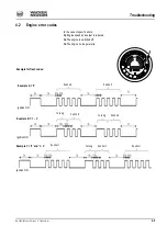
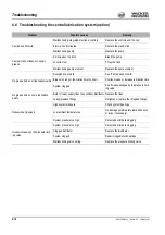
Engine error codes

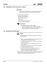
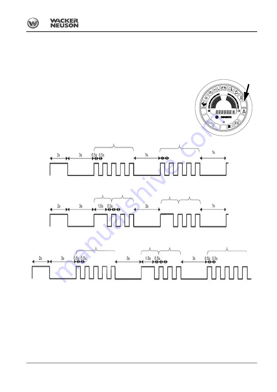
In the case of specific errors: 

Engine speed and output is reduced.

The engine is switched off.

The engine no longer starts.

Example C = ‘5’ and ‘1 – 3’

Example for flash codes:

mph

km/h

DP1

DP2

DP3

DP4

DP5

DP6

DP7

DP8

DP9

DP10

DP24

DP23

DP22

DP21

DP20

DP19

DP18

DP17

DP16

DP15

!

!

5x short

1x long

3x short

Ignition ON

Ignition ON

Example A = ‘5’

Example B = ‘1 – 3’

Ignition ON

1x long

3x short

5x short

5x short

5x short

1x long

3x short

Summary of Contents for 50Z3

Page 1: ...Operator s Manual Track excavators Model E05 01 02 04 05 08 09 Edition 4 3 Language en Article number 1000127717 ...

Page 2: ...o part of this publication may be reproduced translated or used in any form or by any means graphic electronic or mechanical including photocopying recording taping or information storage or retrieval systems without prior permission in writing from the manufacturer The cover features the machine with possible optional equipment Original Operator s Manual Wacker Neuson Linz GmbH Flughafenstr 7 A 4...

Page 3: ...E mark on the type label 1 14 Type labels and component numbers 1 15 Signs and symbols 1 18 Overview of adhesive labels 1 18 Overview of safety labels 1 23 Fire extinguisher 1 28 Safety instructions Identification of warnings and dangers 2 1 Warranty 2 1 Disposal 2 1 Designated use and exemption from liability 2 2 General conduct and safety instructions 2 3 Organizational measures 2 3 Selection an...

Page 4: ...cklist 3 16 Driving the machine 3 17 Preheating start switch 3 17 Throttle 3 17 Automatic engine speed setting 3 18 Before starting the engine 3 19 Starting the engine general 3 20 Starting with the drive interlock internal transponder option from serial no AJ02777 3 21 Jump starting the engine supply battery 3 22 Starting at low temperatures 3 23 When the engine has started 3 23 Special instructi...

Page 5: ...rgency exit on machines equipped with protective Front Guard structures option 3 49 Front window up to serial no AD06526 3 50 Front window from serial no AD06527 3 51 Opening the front window 3 51 Closing the front window 3 52 Opening the lower front window 3 53 Closing the lower front window 3 53 Opening the whole front window 3 54 Closing the whole front window 3 55 Opening the front window to a...

Page 6: ...3 86 Swivel unit brake 3 86 Changeover valve for SAE ISO controls option 3 87 Left hand control lever 3 87 Right hand control lever 3 87 Directional valve position 3 87 Directional valve 3 88 Control lever with proportional controls option overview 3 89 Function 3 89 Left hand control lever 3 90 Changeover between auxiliary hydraulics and boom swivel 3 90 Switching the status indicator on off for ...

Page 7: ...r applications 3 115 Fastening loads 3 115 Work area assessment and preparation 3 115 Examining the site 3 115 Preparing the ground 3 115 Working with the machine 3 116 Working with the standard bucket 3 116 Inadmissible work 3 116 Work position of machine 3 117 Bucket position when digging 3 118 Excavating trenches 3 118 Loading 3 119 Grading 3 119 Excavating trenches sideways 3 119 Working along...

Page 8: ...20 Maintenance 5 23 Oils and fuels 5 24 Troubleshooting 5 24 Warranty 5 24 V belt 5 25 Checking V belt tension 5 25 Retightening the V belt 5 26 Checking the V belt of the air conditioning system option 5 27 Tightening the V belt of the air conditioning system 5 27 Hydraulic system 5 28 Specific safety instructions 5 28 Checking the hydraulic oil level 5 29 Adding hydraulic oil 5 30 Important noti...

Page 9: ...unction 5 51 Status LEDs 5 51 Adjusting cycle time and lubrication time 5 52 Repair in case of clogging 5 52 Preparatory work before taking out of service 5 53 Maintenance if the machine is out of service for a longer period of time 5 53 Putting into operation again 5 53 Fluids and lubricants 5 54 Oil grades for the diesel engine depending on temperature 5 55 Additional oil change and filter repla...

Page 10: ...y table 50Z3 VDS short stick option 6 23 Lift capacity table 50Z3 VDS short stick counterweight option 6 24 Lift capacity table 50Z3 VDS long stick option 6 25 Lift capacity table 50Z3 VDS long stick counterweight option 6 26 Lift capacity table 6003 6 27 Lift capacity table 6003 counterweight option 6 28 Lift capacity table 6003 long stick option 6 29 Lift capacity table 6003 long stick counterwe...

Page 11: ...ng the fuel system 5 5 Cab air filter 5 14 Central lubrication system option 5 51 Checking the coolant level 5 10 Checking the engine oil level 5 7 Checking the hydraulic oil level 5 29 Cleaning 5 40 Diesel particulate filter option 5 16 Electrical system 5 37 Engine and hydraulics cooling system 5 9 Engine lubrication system 5 7 Filter element of air conditioning system option 5 15 Fluids and lub...

Page 12: ...orizontal adjustment 3 38 3 40 3 43 Seat depth adjustment 3 40 3 43 Weight adjustment 3 38 3 40 3 43 Seat belt 3 45 Seat belt height adjustment 3 45 Shatter protection 3 57 Side window 3 56 Specifications 6 1 Chassis 6 1 Dimensions 6 11 Electrical system 6 3 Engine 6 1 Noise levels 6 6 Operating hydraulics 6 2 Vibration 6 6 Starting aid 3 22 T Tilting the upper carriage 3 97 Track maintenance 5 33...

Page 13: ...pter Safety Instructions in particular As a rule keep the following in mind Notice Careful and prudent working is the best way to avoid accidents Operational safety and readiness of the machine do not only depend on your skill but also on maintenance and servicing of the machine This is why regular maintenance and ser vice work is absolutely necessary Extensive maintenance and repair work must alw...

Page 14: ...vity Follow the steps in the recommended order Identifies an activity Description of the effects or results of an activity This symbol shows the driving direction for better orientation in figures and graphics Notice Unless otherwise specified all indications made in this Operator s Manual refer to models 50Z3 6003 and 50Z3 2 6003 2 ...

Page 15: ...orking light on boom 3 Travel gear 4 Stabilizer blade 5 Engine cover 6 Handles 7 Tank filler inlet 8 Exhaust pipe 9 Eye hook for loading tying down the machine 10 Rotating beacon option 11 Auxiliary hydraulics 12 Tank cover 13 Door arrester 14 Door handle and lock 15 Counterweight option 1 3 5 9 2 7 10 8 4 6 11 8 1 12 13 14 15 11 ...

Page 16: ...atellite Travelling drive The diesel engine permanently drives a twin axial variable displacement pump whose oil flow is sent to the control valve Depending on actuation each pump supplies a hydraulic motor or the work hydraulics with oil Work hydraulics The twin axial variable displacement pump supplies the work hydraulics for the main com ponents with oil This pump is output controlled and suppl...

Page 17: ...110 fm 1 5 Introduction Cab The cab has been specially designed for protection in case of an accident ROPS Roll Over Protective Structure and TOPS Tip Over Protective Structure tested cab FOPS Falling Object Protective Structure option ...

Page 18: ...0Z3 6003 Required for operation of the Wacker Neuson quickhitch system Easy Lock quickhitch 81 kg 178 57 lbs 50Z3 6003 Powertilt with Easy Lock 187 kg 412 26 lbs 50Z3 6003 Hammer console 62 kg 136 69 lbs 50Z3 6003 Backhoe bucket 340 mm 13 39 in 79 kg 174 17 lbs 0 058 m 2 05 ft 50Z3 103 kg 227 08 lbs 0 058 m 2 05 ft 50Z3 Mechanical quickhitch 92 kg 202 83 lbs 0 058 m 2 05 ft 6003 104 kg 229 28 lbs ...

Page 19: ...ickhitch 132 kg 291 lbs 0 174 m 6 14 ft 50Z3 6003 Easy Lock quickhitch Ditch cleaning bucket 1 4 m 55 11 in 145 kg 319 67 lbs 0 238 m 8 40 ft 50Z3 6003 187 kg 412 26 lbs 0 238 m 8 40 ft 50Z3 6003 Mechanical quickhitch 147 kg 324 08 lbs 0 205 m 7 24 ft 50Z3 6003 Easy Lock quickhitch Ditch cleaning bucket 1 5 m 59 05 in 155 kg 557 77 lbs 0 220 m 7 77 ft 50Z3 6003 Easy Lock quickhitch Offset bucket 1...

Page 20: ...ents 18 years or older Physically and mentally suited for this work Persons have been instructed in driving and servicing the earth moving machine and have proven their qualifications to the contractor Persons are expected to perform work reliably Users have been appointed by the contractor for driving and servicing the earth moving machine Get informed on and follow the legal regulations of your ...

Page 21: ...he requirements of further pertinent EC Directives and standards The following standards and or technical specifications have been used for the proper application of the requirements regarding safety and health stated in the EC Directives EN 474 1 EN 474 3 EN 12100 1 EN 12100 2 ISO 3471 EN 13510 Place of storage of technical documentation Wacker Neuson Linz GmbH Department R D Haidfeldstr 37 A 406...

Page 22: ...ective 2006 42 EC appendix XI Fachausschüsse Bau und Tiefbau Prüf und Zertifizierungsstelle im BG PRÜFZERT Landsberger Str 309 D 80687 Munich Distinguishing EU number 0515 Notified body according to Directive 2000 14 EC appendix VI TÜV SÜD Industrie Service GmbH Westendstr 199 D 80686 Munich Directives and standards We hereby declare that this product corresponds to the relevant regulations and re...

Page 23: ...Bau und Tiefbau Prüf und Zertifizierungsstelle im BG PRÜFZERT Landsberger Str 309 D 80687 Munich Distinguishing EU number 0515 Notified body according to Directive 2000 14 EC appendix VI TÜV SÜD Industrie Service GmbH Westendstr 199 D 80686 Munich Directives and standards We hereby declare that this product corresponds to the relevant regulations and requirements of the following Directives and st...

Page 24: ...he requirements of further pertinent EC Directives and standards The following standards and or technical specifications have been used for the proper application of the requirements regarding safety and health stated in the EC Directives EN 474 1 EN 474 3 EN 12100 1 EN 12100 2 ISO 3471 EN 13510 Place of storage of technical documentation Wacker Neuson Linz GmbH Department R D Haidfeldstr 37 A 406...

Page 25: ...ective 2006 42 EC appendix XI Fachausschüsse Bau und Tiefbau Prüf und Zertifizierungsstelle im BG PRÜFZERT Landsberger Str 309 D 80687 Munich Distinguishing EU number 0515 Notified body according to Directive 2000 14 EC appendix VI TÜV SÜD Industrie Service GmbH Westendstr 199 D 80686 Munich Directives and standards We hereby declare that this product corresponds to the relevant regulations and re...

Page 26: ... Bau und Tiefbau Prüf und Zertifizierungsstelle im BG PRÜFZERT Landsberger Str 309 D 80687 Munich Distinguishing EU number 0515 Notified body according to Directive 2000 14 EC appendix VI TÜV SÜD Industrie Service GmbH Westendstr 199 D 80686 Munich Directives and standards We hereby declare that this product corresponds to the relevant regulations and requirements of the following Directives and s...

Page 27: ...s en charge Operating weight Transportgewicht transport weight poids en transport Transport weight G Gew GWR PTAC Gross weight rating admissible Max Nutzlast max payload max charge utile Maximum payload Zul Achslast vorne front GAWR PNBE AV Front gross axle weight rating Zul Achslast hinten rear GAWR PNBE AR Rear gross axle weight rating EWG Nr CEE no EEC check number Baujahr model year année fabr...

Page 28: ...fm Introduction Engine number The type label arrow is located on the valve cover engine Example Yanmar 46557 Fig 6 Diesel engine number Fig 6 Diesel engine type label up to serial no AH00578 Fig 6 Diesel engine type label from serial no AH00579 ...

Page 29: ... 5003b110 fm 1 17 Introduction Hydraulic quickhitch Powertilt with hydraulic quickhitch The type label is located on the rear side of the hydraulic quickhitch fork Fig 7 Type label hydraulic quickhitch Fig 8 Powertilt type label ...

Page 30: ...1 18 BA 50Z3 6003 en Edition 4 3 5003b110 fm Introduction 1 13 Signs and symbols Overview of adhesive labels ...

Page 31: ... 3 45 Tying down the machine on page 3 72 Location On either side of the stabilizer blade and on either side of the undercarriage Meaning Noise levels produced by the machine LWA sound power level see chapter 6 10 Noise levels on page 6 6 Location At the front on the chassis Meaning This label shows the forward driving direction Location On either side of the travel gear Meaning Hydraulic oil tank...

Page 32: ...tick functions control pattern B Check before starting the machine the operating pattern that has been chosen see chapter 3 51 Changeover valve for SAE ISO controls option on page 3 87 Location On the headliner Meaning The admissible lift capacity must be observed according to the table see chapter 6 20 Lift capacity table 50Z3 on page 6 19 Location On the headliner Meaning option This label descr...

Page 33: ...s see chapter 3 50 Control levers ISO controls overview on page 3 83 Location Cab roof lining Meaning up to serial no AH02781 This label describes the pedal and control lever functions control pattern A see chapter 3 50 Control levers ISO controls overview on page 3 83 Location On the headliner Controls A ISO controls B SAE controls Meaning from serial no AJ02777 This label describes the pedal and...

Page 34: ...17 Location Below the throttle lever Meaning up to serial no AH01643 Describes the stabilizer blade lever function Location Inside the cab Meaning The Powertilt function is enabled once the machine is started The 3rd control circuit is disabled The 3rd control circuit is enabled with the button on the right hand control lever The status indicator light illuminates The function is performed with th...

Page 35: ...BA 50Z3 6003 en Edition 4 3 5003b110 fm 1 23 Introduction Overview of safety labels ...

Page 36: ...for example engine cover fan guard Location On the chassis on the right Meaning This safety label warns of the following dangers Caution rotating fan Stop the engine before opening the engine cover Stay clear of the engine compartment if the fan is still running Caution danger of severe crushing Stay clear of the engine compartment with the engine running Perform work in the engine compartment at ...

Page 37: ...fore starting the machine The machine may be put into operation only if you read understand and observe the Operator s Manual Location Inside the cab on the side Meaning Caution danger of severe crushing 1 Always use the handles to open and close the front window 2 Always lock the front window with both locks 3 Ensure that no one hits the window with their head as you open and close it Location On...

Page 38: ...lewing range during operation Location At the rear of the cab near the handle Meaning Caution danger of severe crushing of body Stay clear of the machine s work range during operation Location At the front of the chassis near the swivelling console Meaning Caution danger of putting the machine into operation unintentionally Danger of severe or fatal injuries Stop the engine before performing maint...

Page 39: ...hine Location On either side of the boom Meaning up to serial no AH01643 Hydraulic oil tank under pressure see Adding hydraulic oil on page 5 30 Location On the hydraulic oil tank Meaning up to serial no AH01643 Press the boom and the stabilizer blade into the ground as you leave the machine remove the ignition key and place chocks on the left and right under the tracks see chapter Parking checkli...

Page 40: ...uipment nor is it available as an option from Wacker Neuson Retrofitting a fire extinguisher according to DIN EN 3 must be performed by an author ized workshop Notice Check the fire extinguisher at regular intervals also ensure that it is safely installed Fig 48 Fire extinguisher up to serial no AH02781 Fig 49 Fire extinguisher from serial no AJ02777 ...

Page 41: ...l can cause damage to the environment The environment is in danger if environmentally hazardous material waste oil for example is not subject to proper use or disposal 2 2 Warranty Warranty claims can be made only if the conditions of warranty have been observed They are included in the General Conditions of Sales and Delivery for new machines and spare parts sold by the dealers of Wacker Neuson L...

Page 42: ...ntenance and service conditions The safety of the machine can be negatively affected by performing machine modifica tions without proper authority and by using spare parts equipment attachments and optional equipment that have not been checked and released by Wacker Neuson GmbH Wacker Neuson will not be liable for damage resulting from this Wacker Neuson Linz GmbH shall not be liable for injury an...

Page 43: ...structions including those relevant to super vising and reporting duties Persons entrusted with work on the machine must have read and understood the Operator s Manual and in particular chapter Safety Instructions before beginning work This applies especially to persons working only occasionally on the machine for example set up or maintenance The user owner must check at least from time to time w...

Page 44: ...repair Define the machine operator s responsibilities also with regard to observing traffic regulations Give the operator the authority to refuse instructions by third parties that are contrary to safety Do not allow persons to be trained or instructed or persons taking part in a general training course to work on or with the machine without being permanently supervised by an experienced person Wo...

Page 45: ...machine immediately and lock it Have any defects rectified immediately Start and operate the machine from the seat only Perform start up and shut down procedures in accordance with the Operator s Manual and observe the indicator lights Before putting the machine attachment into operation start up moving ensure that no one is at risk by putting the machine attachment into operation Before driving w...

Page 46: ...el does not come into contact with hot parts Do not smoke during refuelling and avoid fire and sparks Switch off the machine before refuelling Do not smoke Never get on or off a moving machine and never jump off the machine Should the lights of the machine not be sufficient for performing work safely provide additional lighting of the work area Installed work lights must not be switched on for tra...

Page 47: ...ersing the machine risk of accidents Persons in the blind spot of the machine cannot be seen by the user Ensure that nobody is within the risk zone of the machine when changing the driving direction Use the rearview mirrors to reverse with the machine 2 10 Trailer operation Notice No trailer operation with this machine ...

Page 48: ...t is not possible to unhook the sling unintentionally Position the lifting gear ensuring the sling is not deflected by other parts Do not use any lifting gear and slings that are damaged or not of sufficient size The lifting gear must be designed to withstand the loads that can arise in the different positions of the work equipment or parts of the boom Lateral loads and diagonal tensile forces mus...

Page 49: ...ffect handling and the machine s steering capability Fit the attachments with the specially required devices only Before uncoupling or coupling hydraulic lines hydraulic quick couplers Stop the engine Release the pressure in the hydraulic system In order to do so move the control levers of the hydraulic control units back and forth a couple of times Coupling attachments requires special care Secur...

Page 50: ...topped the ignition key is removed and the machine has been secured against unintentional movement Should maintenance or repair be inevitable with the engine running Only work in groups of two Both persons must be authorized for the operation of the machine One person must be seated on the seat and maintain visual contact with the other person Observe the specific safety instructions in the work m...

Page 51: ...arts dangerous for life and limb bruising cutting always ensure safe blocking support of these areas Perform maintenance and repair work beneath a raised machine attachments or additional equipment only if a safe and secure support has been provided for the sole use of hydraulic rams jacks etc does not sufficiently secure raised machines or equipment attachments Avoid contact with hot parts such a...

Page 52: ... Before starting any work the machine operator must ensure that there are no lines in the work area If you are not sure contact the person in charge at the network operator If there are lines take the following safety measures Mark the position and path of the lines unambiguously Fasten support or secure exposed lines Safely fasten lines if vibration or shocks to these lines must be avoided Workin...

Page 53: ...ck all lines hoses and threaded fittings regularly for leaks and visible damage Repair any damage and leaks immediately Splashed oil can cause injury and fire In accordance with the Operator s Manual instructions for the respective assembly release the pressure in all system sections and pressure lines hydraulic system to be opened before performing any implementing repair work Hydraulic and compr...

Page 54: ... the canopy shatter protection option on page 3 57 Safety instructions see chapter 2 5 General conduct and safety instructions on page 2 3 If there is a risk of material coming off in fragments and splinters for example when working with a hydraulic hammer a suitable protection for example a protective screen or another suitable protective facility must be installed on the machine During operation...

Page 55: ...thout any resistance Do not use the hammer to raise loads Do not hit the hammer against rocks concrete etc Do not raise the machine with the boom Do not perform any movements with the machine during hammer operation Working with the rams and or the boom fully extended is not allowed Do not swivel the Powertilt unit beyond 30 during hammer operation oth erwise the load on the boom increases enormou...

Page 56: ...2 16 BA 50Z3 6003 en Edition 4 3 5003b210 fm Safety instructions ...

Page 57: ...ator lights and controls in the cab The pages stated in the table refer to the description of the controls A combination of digits or a combination of digits and letters for example 40 18 or 40 A used for identifying the control elements means fig no 40 control element no 18 or position A in fig no 40 Figures carry no numbers if they are placed to the left of the text ...

Page 58: ...3 2 BA 50Z3 6003 en Edition 4 3 5003b320 fm Operation 3 1 Cab 50Z3 6003 up to serial no AH02781 4 8 17 13 11 6 18 12 14 1 3 2 5 10 9 7 15 16 20 24 23 25 26 19 21 22 29 27 28 ...

Page 59: ...ustment 3 38 10 Air vent rear window on the left 11 Air vent rear window on the right 12 Radio option 13 Seat backrest adjustment 3 38 14 Seat belt lock 3 45 15 Cup holder 16 Document storage bin 17 Switch panel 3 6 18 Throttle 3 17 19 Fuse box 6 3 20 Preheating start switch 3 17 21 Cigarette lighter 22 Round display element 3 6 23 Drive pedal left 3 24 24 Drive pedal right 3 24 25 Drive lever lef...

Page 60: ...3 4 BA 50Z3 6003 en Edition 4 3 5003b320 fm Operation 3 2 Cab 50Z3 2 6003 2 from serial no AJ02777 15 16 24 25 26 27 23 17 11 6 12 14 19 13 3 2 5 7 1 20 21 18 29A 9 10 8 22 28 4 29B 29B 15 ...

Page 61: ... rear window on the right 12 Radio option 13 Seat backrest adjustment 3 38 14 Seat belt lock 3 45 15 Cup holder 16 Document storage bin 17 Switch panel 3 6 18 Throttle 3 17 19 Fuse box 6 3 20 Preheating start switch 3 17 21 Cigarette lighter 22 Round display element 3 6 23 Drive pedal left 3 24 24 Drive pedal right 3 24 25 Drive lever left 3 24 26 Drive lever right 3 24 27 Stabilizer blade lever p...

Page 62: ... BA 50Z3 6003 en Edition 4 3 5003b320 fm Operation 3 3 Control elements 50Z3 up to serial no AH02781 6003 up to serial no AH00578 30 34 33 31 32 35 36 37 38 41 43 42 44 45 46 48 49 50 51 52 39 47 40 40 40 ...

Page 63: ... 3 4 Control elements 6003 serial nos AH00579 to AH02750 mph km h DP1 DP2 DP3 DP4 DP5 DP6 D P7 D P 8 D P 9 D P 1 0 DP24 DP23 DP22 DP21 DP20 DP19 D P18 D P 1 7 D P 1 6 D P 1 5 40 34 35 31 40 30 32 37 39 43 42 44 45 46 48 49 40 53 54 40 36 41 51 47 52 38 50 ...

Page 64: ...mperature too high 3 12 37 Indicator light red safe load indicator 3 12 38 Fuel level indicator 3 13 39 Hour meter 3 12 40 Not assigned 41 Coolant temperature indicator 3 13 42 High speed 3 25 43 Washer system 3 36 44 Working lights 3 30 45 Roof lights option 3 32 46 Rotating beacon option 3 32 47 Automatic engine speed setting option 3 18 48 Ventilation 3 33 49 Air conditioning option 3 37 50 Saf...

Page 65: ...no AJ02777 mph km h DP1 DP2 DP3 DP4 DP5 DP6 D P7 D P 8 D P 9 D P 1 0 DP24 DP23 DP22 DP21 DP20 DP19 D P18 D P 1 7 D P 1 6 D P 1 5 40 34 35 31 40 30 32 37 39 43 42 44 45 46 48 49 40 53 54 40 36 41 55 47 52 38 50 Switch panel on left hand control lever base Switch panel on right hand control lever base 56 ...

Page 66: ...ad indicator 3 12 38 Fuel level indicator 3 13 39 Hour meter 3 12 40 Not assigned 41 Coolant temperature indicator not equipped 3 13 42 High speed 3 25 43 Washer system 3 36 44 Working lights 3 30 45 Roof lights option 3 31 46 Rotating beacon option 3 32 47 Automatic engine speed setting option 3 18 48 Ventilation 3 33 49 Air conditioning option 3 37 50 Safe load indicator option 3 113 51 Not assi...

Page 67: ...ight red alternator charge function The V belt is malfunctioning or there is an error in the charging circuit of the alternator if the indicator light illuminates with the engine running The battery is no longer charged Caution The coolant pump no longer runs if the V belt is faulty Danger of engine overheating or breakdown If the indicator light illuminates with the engine running Stop the engine...

Page 68: ...loves and clothing Open the cap to the first notch and release the pressure Indicator light red safe load indicator option Illuminates after reaching the authorized payload or load torque Reduce the load until the indicator light goes out Indicator light yellow cold starter Illuminates if the key in the preheating start switch is in position 2 A glow plug preheats the air in the combustion chamber...

Page 69: ... of fuel in the tank Coolant temperature indicator Indicates the current coolant temperature of the machine mph km h DP1 DP2 DP3 DP4 DP5 DP6 D P7 D P 8 D P 9 D P 1 0 DP24 DP23 DP22 DP21 DP20 DP19 D P18 D P 1 7 D P 1 6 D P 1 5 7 D P 8 D P 9 D P 1 0 DP24 DP23 DP22 DP21 DP20 DP19 D P18 D P 1 7 D P 1 6 D P 1 5 ...

Page 70: ...al before putting the machine into operation The machine may only be used in technically perfect condition in accordance with its designated use and the instructions set forth in the Operator s Manual and only by safety conscious persons who are fully aware of the risks involved in operating the machine Go through the Start up checklist in the following chapter Running in period Handle the machine...

Page 71: ...ugh fuel in the tank 5 3 2 Coolant level OK 5 10 3 Remove water in the diesel fuel prefilter 5 6 4 Engine oil level OK 5 7 5 Oil level in hydraulic tank OK 5 29 6 Water level in washer tank OK 3 36 7 V belt condition and tension checked 5 25 8 Lubrication points greased 5 36 9 Tracks checked for cracks cuts etc 5 33 10 Lights signals indicators warning lights and indicator lights OK 3 30 11 Dirt f...

Page 72: ...ature indicator for engine coolant in normal range 3 12 3 13 3 Anyone dangerously close to the machine 4 Do the drive pedals and control levers work correctly 3 24 No Question 1 Attachments lowered to the ground 3 82 2 Stabilizer blade lowered to the ground 3 Control lever base folded up 3 60 4 Cab locked especially if the machine cannot be supervised 3 58 When parking on public roads 5 Machine ad...

Page 73: ...ing start switch 20 Position Function Power consumer 0 Insert or remove the ignition key None 1 ON drive position Feed pump switched on Indicator lights illuminate All functions are operational Indicator lights illuminate Shrill sound 2 Preheats the engine 10 15 seconds Glow plugs 3 Starts the engine Starter is actuated Indicator lights must go out 18 Fig 54 Throttle from serial no AJ02777 18 Fig ...

Page 74: ...m serial no AH00579 option 6003 from serial no AH00645 standard Diesel engine speed is automatically reduced to idling after 5 seconds if no hydraulic func tions are performed and if the automatic engine speed setting option is enabled As soon as a hydraulic function is performed with the control levers diesel engine speed is automatically increased again to the engine speed adjusted with the thro...

Page 75: ...lation on enclosed premises Adjust seat position and rearview mirror see chapter 3 23 Seat 50Z3 on page 3 37 Fasten your seat belt see chapter 3 26 Seat belt on page 3 45 Fold the left hand control lever base down Check whether all levers and pedals are in neutral position Move the throttle to the centre position between minimum and maximum if the engine is cold Remove dirt for example mud snow ic...

Page 76: ...r lights illuminate Replace malfunctioning indicator lights immediately Turn the ignition key to position 2 and hold it in this position for about 5 seconds The intake air is preheated Turn the ignition key to position 3 and hold it in this position until the engine starts If the engine does not start after 10 seconds Stop starting the engine and try again after 30 seconds If the engine still does...

Page 77: ...ert the new key or the key requiring coding in the preheating start switch and turn it to position 1 within 15 seconds This action registers the key The procedure is automatically cancelled if no key requiring coding is detected within 15 seconds Several keys requiring coding can be inserted one after another in the preheating start switch Each key must then remain at least 1 second in position 1 ...

Page 78: ...edure Drive the jump starting vehicle close enough to the machine so that the jump leads can reach to connect the two batteries Let the engine of the jump starting vehicle run First connect one end of the red jump lead to the terminal of the flat battery then connect the other end to the terminal of the starting battery Connect one end of the black jump lead to the terminal of the starting battery...

Page 79: ...d conditions Therefore ensure that the battery is always well charged 3 14 When the engine has started Check whether all indicator lights have gone out Let the engine warm up At cold temperatures Increase the engine speed slowly Do not run the engine at full load until it has reached its operating temperature Engine warm up After the engine has started allow it to warm up at slightly increased idl...

Page 80: ... the rear Risk of accidents Bear in mind the stabilizer blade s position The stabilizer blade side is the front side Raise the boom and the stabilizer blade The machine can be moved either with the drive levers or with the pedals Lock the upper carriage when travelling over longer distances 3 Forward or reverse drive speed depends on the position of the drive levers or the drive pedals and of the ...

Page 81: ...n affect machine handling when cornering Moving off Notice The machine will not move off unless the left hand control lever is folded down After starting the engine The alternator charge indicator light goes out Press the drive pedal slowly Machine moves off Hydraulic brake The pedals automatically return to their initial positions as soon as they are released This creates sufficient hydraulic bra...

Page 82: ...on Perform slow and smooth drive movements Avoid sudden drive movements Reduce the engine speed Do not use high speed Avoid reversing when driving downhill Drive slowly on slippery ground for example meadows leaves wet steel plates and ice The machine can slip even if the ground is level If the engine stops as you drive across a slope immediately put the control levers to neutral position and star...

Page 83: ...y take more time but is decisively safer Caution Travelling diagonally on slopes is forbidden Do not exceed a maximum longitudinal inclination of 15 This applies for example to driving on Slopes Hollows Obstacles Caution Danger of tipping over Do not exceed a maximum lateral inclination of 10 This applies for example to driving on Slopes Hollows Obstacles Caution Danger of tipping over Fig 65 Driv...

Page 84: ...lizer blade is over lower it to the ground Caution Lowering the stabilizer blade too deeply into the ground can create a high resistance Slightly raise the stabilizer blade The clearance between the stabilizer blade and the ground should be about 1 cm 0 39 The stabilizer blade can also be operated with the pedal Notice Check the position of the stabilizer blade before driving the machine Fig 69 St...

Page 85: ... Operate the joystick repeatedly to release the pressure in the hydraulic system Remove the ignition key and carry it with you Raise the control lever base Close the windows and doors Leave the cab Close and lock all covers Secure the tracks accordingly for example chocks etc Notice Secure the machine against unauthorized operation Raise the control lever base Remove the ignition key and carry it ...

Page 86: ... the working light in poor light conditions or during the night Fig 72 Working light switch up to serial no AH02781 44 44 Fig 72 Working light switch from serial no AJ02777 Working lights ON Press switch 44 down The working light illuminates the indicator light in switch 44 illuminates OFF Press switch 44 up The working light goes out the indicator light in switch 44 goes out ...

Page 87: ...5 Fig 73 Roof lights switch from serial no AJ02777 45 Roof lights option 1st position Press switch 45 to the 1st position The front roof lights and the indicator light in the switch illuminate 2nd position Press switch 45 to the 2nd position Both front roof lights and the rear roof light illuminate OFF Press switch 45 up All roof lights are switched off The indicator light in the switch goes out F...

Page 88: ...lations of your country for operating the rotating beacon Fig 75 Rotating beacon switch up to serial no AH02781 46 Fig 75 Rotating beacon switch from serial no AJ02777 46 Rotating beacon option ON Press switch 46 down The rotating beacon illuminates OFF Press switch 46 up The rotating beacon is switched off ...

Page 89: ...r the cab from time to time Notice The best defrosting results for the front window are achieved by opening both noz zles at the front right and in the leg room Direct the nozzles to the front window Fig 76 Air circulation in cab up to serial no AH02781 1 2 48 Ventilation fresh air 1st posi tion Press switch 48 down one step Low fan speed 2nd posi tion Press switch 48 down two steps High fan speed...

Page 90: ...9 Engine cover on page 3 63 Notice Summer and winter operation does not depend on the season adjust according to personal requirements Heating controls from serial no AD04651 Cooling Turn heater valve 1 toward A until you reach the required temperature Heating Turn heater valve 1 toward B until you reach the required temperature Notice In order to reach the required temperature quickly we recommen...

Page 91: ...he cab is taken in and cooled and a small amount of fresh air is added If recirculated air mode is switched off only fresh air is used for heating ventilating or cooling the cab Notice Open the windows and the door so the hot air can escape Then switch on air con ditioning and close the windows and the doors Keep all windows and doors closed to achieve best cooling results Fig 80 Air conditioning ...

Page 92: ...ze instructions for further information on concentrations The rubber diaphragm in the non return valve in the housing conglutinates if stored in a dry condition over a longer period of time In order to restore this valve s function moisten this non return valve dip it briefly in water and then blow air through it Fig 82 Front wiper switch up to serial no AH02781 1 2 43 Fig 82 Front wiper switch fr...

Page 93: ...e machine Caution Adjusting the backrest can damage the rear window Ensure that the backrest does not touch the rear window as you adjust backrest inclination Select a seat position which will not damage the window when working with the machine Notice Adjust the seat to the operator s weight before putting the machine into operation Adjust the seat suspension correctly to ensure a high level of ri...

Page 94: ... downward Raise the seat as far as it will go then Lower the seat to the lowest position Horizontal adjustment Sit down on the seat Pull lever 9 upward and at the same time Move the seat forward or backward Backrest adjustment Sit down on the seat Pull lever 13 upward and at the same time Lean back to push the backrest into the required position Let lever 13 lock into place Fig 85 Weight adjustmen...

Page 95: ...ndow Ensure that the backrest does not touch the rear window as you adjust backrest inclination Select a seat position which will not damage the window when working with the machine Notice Adjust the seat to the operator s weight before putting the machine into operation Adjust the seat suspension correctly to ensure a high level of ride comfort A weight adjustment B horizontal adjustment C seat d...

Page 96: ... must engage in the required position Seat depth adjustment Sit down on the seat Pull lever C upward and at the same time Move the seat surface forward or backward The lever must engage in the required position Backrest adjustment Sit down on the seat Adjust by pulling lever D in the direction of the arrow Lean back to push the backrest into the required position The lever must engage in the requi...

Page 97: ...d rest forward or backward Height adjustment Raise the seat with force Let the seat engage audibly in one of the three positions The seat is lowered to the lowest position if it is raised beyond the last position Upward Raise the seat as required until it engages audibly downward Raise the seat as far as it will go then Lower the seat to the lowest position Fig 93 Head rests Fig 94 Height adjustme...

Page 98: ... rear window as you adjust backrest inclination Select a seat position which will not damage the window when working with the machine Notice Adjust the seat to the operator s weight before putting the machine into operation Adjust the seat suspension correctly to ensure a high level of ride comfort Notice Adjust weight and height only with the ignition switched on or the machine started A weight a...

Page 99: ...ure minimum spring travel Notice Do not actuate more than one minute in order not to damage the compressor Horizontal adjustment Sit down on the seat Pull lever B upward and at the same time Move the seat forward or backward The lever must engage in the required position Seat depth adjustment Sit down on the seat Pull lever C upward and at the same time Move the seat surface forward or backward Th...

Page 100: ...d rest can be adjusted vertically by raising or lowering it in notched positions Inclination can be adjusted by pressing the head rest forward or backward Horizontal suspension Shocks in driving direction are absorbed more easily Slide the seat fully back to enable the horizontal suspension Fig 100 Backrest adjustment D Fig 101 Head rests Fig 102 Horizontal suspension Pos Function 1 Horizontal sus...

Page 101: ...ter an accident the belt strap is stretched and no longer serviceable even if no optical defects can be detected In a further accident the seat belt Will not provide adequate protection Replace the seat belt after every accident Have fastening points and seat fixture checked for bearing capacity Seat belt 14 is for the user s safety during work on construction sites and during road travel Fastenin...

Page 102: ...k the condition of the seat belt regularly Have damaged seat belt elements immediately replaced by a workshop Always keep the seat belt clean as coarse dirt can impair proper functioning Seat belt buckle must not be obstructed by foreign bodies paper or sim ilar otherwise the buckle latch cannot lock into place After an accident the belt strap is stretched and no longer serviceable even if no opti...

Page 103: ...isk of injury Use safety oriented ladders and work platforms for adjustment work on the machine Never use machine parts or attachments superstructures as a climbing aid Do not adjust the mirrors when driving the machine Immediately replace damaged or broken mirrors Additional equipment or attachments must not impair visibility Danger In spite of the visual aids mirrors not the entire area around t...

Page 104: ... to road travel position before adjusting the mirrors see Drive position on page 3 24 Adjusting the mirrors Notice We recommend having the mirrors adjusted by a second person Left and right hand outside mirrors of cab Adjust the mirrors in order to Ensure sufficient visibility from the seat onto the drive and work area Ensure maximum visibility to the rear Ensure visibility of the rear left edge o...

Page 105: ... on page 3 56 Opening the front window completely see chapter 3 30 Front window up to serial no AD06526 on page 3 50 see chapter 3 31 Front window from serial no AD06527 on page 3 51 Emergency exit on machines equipped with protective Front Guard structures option The rear window can be used as an emergency exit if the door is blocked The rear win dow is broken with emergency hammer A fastened ove...

Page 106: ...w is fitted with a lever Push levers A down on either side Pull the front window upward with handles B The front window must lock into rails C on either side Lock with levers A on either side in C Pull levers A to the rear to do this Check whether both levers A are actually locked in rails C Lowering the front window Push levers A forward on either side Pull the front window downward with handles ...

Page 107: ...close it Always open and close the front window by means of both handles B Levers A must always engage in the locks as you open and close the window Fold up the control lever base before opening or closing the front window in order to avoid any unintentional operation or movement of the machine Opening the front window Keep levers A pressed on the left and right and pull the front window upward wi...

Page 108: ...in both recesses C Closing the front window Press levers A on the left and right and pull the front window downward with both han dles B Press levers A on either side and engage them in the lock C A Fig 114 Opening the front window Fig 115 Closing the front window A B Fig 116 Closing the front window A ...

Page 109: ...upward with both handles E Make levers D lock into both recesses F Closing the lower front window Keep levers D on the left and right pressed and pull the lower front window downward Release levers D and make them lock into place on either side Fig 117 Lower front window Fig 118 Opening the lower front window D F E Fig 119 Closing the lower front window D ...

Page 110: ... handles E Make levers D lock into both recesses F Keep levers A pressed on the left and right and pull the entire front window upward with both handles B Release levers A and make them lock into place in both recesses C Fig 120 Whole front window Fig 121 Opening the whole front window D F E Fig 122 Opening the whole front window A B C A Fig 123 Opening the front window ...

Page 111: ...ndow downward with both handles B Press levers A on either side and make them lock into place Keep levers D on the left and right pressed and pull the lower front window downward Release levers D and make them lock into place on either side Fig 124 Closing the front window A B Fig 125 Closing the front window A Fig 126 Closing the lower front window D ...

Page 112: ...o place in both recesses G Close Press levers A on either side close the front window and make it lock into place on either side 3 32 Opening and closing the side window Press button F upward At the same time move the window in the required direction and make it lock into one of the recesses Fig 127 Opening the front window to a gap Fig 128 Opening the front window to a gap G A Fig 129 Side window...

Page 113: ...he ground Lower the stabilizer blade Stop the engine Operate the joystick repeatedly to release the pressure in the hydraulic system Remove the ignition key and carry it with you Raise the control lever base Install shatter protection A from above at points B with the fastening material supplied with it Remove in the reverse order Notice The shatter protection can be combined with a protective Fro...

Page 114: ...e door is locked Unlocking the door Turn the key in door lock A to the right R The door is unlocked Door 6003 Opening the door from the outside Press door handle B Locking the door Turn the key in door lock A to the left L The door is locked Unlocking the door Turn the key in door lock A to the right R The door is unlocked Opening the door from the inside Press down lever C on the inside left on t...

Page 115: ... Operation Securing an open door Press the door against bracket D of arrester E with an audible click Releasing the door arrester Pull button F to release the door from the arrester Fig 134 Door arrester D E Fig 135 Releasing the door arrester F ...

Page 116: ... lever base in the top position Caution Do not use handle A on the control lever base the outside mirror option or its bracket as a support to ease your entrance or exit from the cab Use the entrance handles on the cab Fold control lever base 5 down to position C once you are in the cab The gas strut keeps the control lever base in the lower position Notice Do not adjust the height of the control ...

Page 117: ... Remove the ignition key Move control levers 1 and 2 in all directions repeatedly Caution Do not use handle B on the control lever base the outside mirror option or its bracket as a support to ease your entrance or exit from the cab Use handles A and footholds on the cab Notice When entering or leaving the cab the door must be locked in the arrester see chapter 3 34 Door on page 3 58 VDS foothold ...

Page 118: ...sion spring keeps the control lever base in the lower position 3 37 Armrest adjustment up to serial no AH02764 Caution Ensure that the armrest does not touch the control lever as you fold it up Adjust the armrest to prevent it from touching the control lever Turn tubular turnbuckle nut A to the left B The armrest can be lowered Turn nut A to the right C The armrest can be raised Fig 140 Control le...

Page 119: ...standstill Rotating and moving parts risk of injury Ensure that no one is injured by the open engine cover Opening Press lock A Pull the engine cover upward Closing Firmly press down the engine cover until lock A engages with an audible click Locking and unlocking Lock the engine cover with the ignition key of the preheating start switch Turn the ignition key in lock A to the left L Engine cover l...

Page 120: ...battery master switch Before working on the electrical system Before performing welding work As an antitheft precaution Interrupting power supply Turn key A of the battery master switch to position B and remove it Switching on power supply Insert key A in the battery master switch Turn key A down to the notched position C Fig 144 Battery master switch model 6003 up to serial no AH00578 Fig 144 Bat...

Page 121: ...or lower it Danger Always lock the door Risk of accidents Always close and lock the door when tilting the cab Remove loose objects from the cab Preparations for raising or lowering the cab Stop the engine Remove the ignition key and carry it with you Raise the control lever base left Slackening the securing elements Raise the floor mat Remove lock nuts A and C with a suitable tool Lock nut A is lo...

Page 122: ...at the piston of the lift pump is fully extended and that the valve is closed before lowering the cab Turn valve F of the lift pump clockwise to the right Remove the split pin from guide L Press tilt rod K into guide J Use the handle to lower the cab until it is back on the pump Insert tube D on valve F Slowly turn tube D counterclockwise to the left The cab is lowered by its own weight Caution On...

Page 123: ...3b330 fm 3 67 Operation Notice Replace the lock nuts every time they are slackened Replace the lock nuts Tighten the new lock nuts A and C to 87 Nm 64 lbf ft Put floor mat B back in place Fig 148 Cab lock nut A Fig 149 Cab lock nut C ...

Page 124: ... Use towing bracket A only for towing Secure shackle B with the shackle pin and a lock pin Install a towing bar or cable of adequate size to the towing bore Pull the machine slowly Tow the machine only until the ground conditions allow the machine to move on its own Caution Do not tow a malfunctioning machine otherwise the drive can be damaged The machine must be loaded with a crane see chapter 3 ...

Page 125: ...als The person guiding the crane operator must be within sight or sound of him Danger Incorrect fastening of lifting gear on the machine Risk of accidents Have only experienced persons attach lifting gear Use only the lifting points provided to this effect and marked accordingly for attaching lifting gear Perform a visual check to ensure that all lifting points are in good condition If the machine...

Page 126: ... the attachment Empty or clean and remove the attachment Remove all dirt from the machine Place the machine on firm level and horizontal ground Raise the boom completely Pull the stick toward the machine Move the attachment inward Raise the stabilizer blade Position the boom straight ahead at the centre of the machine Stop the engine Operate the joystick repeatedly to release the pressure in the h...

Page 127: ...le with chocks to prevent it from rolling Place the access ramps at the smallest possible angle Do not exceed a slope of 15 Use access ramps with an antiskid surface only Ensure that the loading area is clear and access to it is not obstructed by superstruc tures for example Ensure that the access ramps and the tracks of the machine are free of dirt oil grease ice etc Start the engine of the machi...

Page 128: ...er with a simple cap or suitable adhesive tape Ensure that the user of the transport vehicle knows the overall height width and weight of his vehicle incl machine before departure as well as the legal transport regulations of the country or countries where transport is to take place 3 46 Travelling signal option Danger Careful when reversing or driving forward Risk of accidents There must be nobod...

Page 129: ...t re use self locking fasteners Definition of FOPS Front Guard categories Category I Protection against small falling objects FOPS or small objects penetrating into the cab from the front Front Guard such as bricks small pieces of concrete tools for machines that are used for repairing roads landscaping work and for working on other construction sites for example Category II Protection against hea...

Page 130: ...nger situation is evaluated and that the national regulations are observed The operator must ensure that only work is performed that does not require any higher protection Accidents cannot be fully avoided despite equipping a machine with protective structures Installing 1 Stop and park the machine Stop the engine 2 A minimum 2 persons are required for installing removing 3 Tighten screws A M10 an...

Page 131: ...ensure that the danger situation is evaluated and that the national regulations are observed The operator must ensure that only work is performed that does not require any higher protection Accidents cannot be fully avoided despite equipping a machine with protective structures Have the initial assembly performed by an authorized workshop 1 Stop and park the machine Stop the engine 2 A minimum 2 p...

Page 132: ...ective Front Guard structure corresponds to category II according to ISO 10262 1998 The operator must ensure that the danger situation is evaluated and that the national regulations are observed The operator must ensure that only work is performed that does not require any higher protection Accidents cannot be fully avoided despite equipping a machine with protective structures 1 Stop and park the...

Page 133: ...A 50Z3 6003 en Edition 4 3 5003b330 fm 3 77 Operation 4 Mounting point B lower 5 Tighten screws C and lock nuts at the upper and lower left and right to 110 Nm 81 ft lbs Fig 160 Lower mounting point B C ...

Page 134: ...nditions of restricted visibility due to rain snowfall dust etc Causes severe injury or death Stop work immediately Notice The shatter protection canopy option protects the driver against fragments from the front The operator must ensure that the danger situation is evaluated and that the national regulations are observed The operator must ensure that only work is performed that does not require a...

Page 135: ...nstalling 1 Stop and park the machine Stop the engine 2 Install remove shatter protection B from the front and fasten remove it at the fas tening points C with the fastening material supplied 3 Tighten screws D at fastening points C to 25 Nm 18 ft lbs Fig 161 Work area with shatter protection A Fig 162 Work area with shatter protection top view Fig 163 Installing the shatter protection symbolic re...

Page 136: ...chapter 3 30 Front window up to serial no AD06526 on page 3 50 see chapter 3 31 Front window from serial no AD06527 on page 3 51 Emergency exit for cab equipped with protective Front Guard structure Danger Danger of injuries due to glass splinters Danger of injuries due to glass splinters when smashing the window with the emergency hammer Only smash windows in an absolute emergency Protect your fa...

Page 137: ... en Edition 4 3 5003b330 fm 3 81 Operation The rear window can be used as an exit if the door is blocked Smash the rear window with emergency hammer A Fig 165 Position of emergency hammer symbolic repre sentation A ...

Page 138: ...nd the structure itself before starting work The building can collapse causing severe injury and damage In general the machine is more liable to tilt if the boom is positioned laterally than if it is positioned at the front or rear of the machine Do not move the attachment across the heads of workers or across the cabs of trucks or of other means of transport Material can fall out or the attachmen...

Page 139: ...wly Left hand control lever Notice Always perform smooth control movements Hammer pedal lock up to serial no AH02781 Danger Do not press the pedal unintentionally Risk of injury In order to avoid unintentional actuation of the pedal fold cover K toward the seat once operation is over Fig 166 Left hand control lever D C A B Position Lever Function A Forward Extends the stick B To the right Rotates ...

Page 140: ...ion is over Triple articulation boom option 6003 Press hammer pedal 2 forward The ram of the triple articulation boom is extended Press hammer pedal 2 backward The ram of the triple articulation boom is retracted Fold cover K toward the seat once operation is over Notice With triple articulation boom option the hammer pedal slides in driving direction and is not installed as shown in Fig 168 Hamme...

Page 141: ... hammer pedal 2 to the right The ram of the triple articulation boom is extended Fold hammer pedal 2 toward the seat once operation is over Right hand control lever Lowering the boom with the engine stopped Ensure that no one is dangerously close to the machine Turn the ignition key to position 1 Press forward and hold the control lever A and E Until the boom is completely lowered Return the contr...

Page 142: ...ments if the bucket is full In order to rotate the upper carriage to the left Push the left hand control lever 3 to the left A The upper carriage rotates to the left In order to rotate the upper carriage to the right Push the left hand control lever 3 to the right B The upper carriage rotates to the right Swivel unit brake Hydraulic swivel unit brake The upper carriage s rotation is sufficiently b...

Page 143: ... hand control lever Right hand control lever Directional valve position The directional valve is located on the left in base plate I of the chassis Fig 176 Left hand control lever SAE controls D C A B 3 Position Lever Function A Forward Lowers the boom B To the right Rotates the upper carriage to the right C Backward Raises the boom D To the left Rotates the upper carriage to the left Fig 177 Righ...

Page 144: ...SAE controls and vice versa Tighten wing nut J after changing the control mode Caution No driving or working with the machine if wing nut J is malfunctioning Immediately contact an authorized workshop to replace a malfunctioning wing nut Fig 179 Directional valve J A B Position Function A ISO controls B SAE controls ...

Page 145: ...ting characteristic curve 1 slow movements In this position the slide switch is not actuated to full output and you can move the machine more smoothly flat characteristic curve If you require the full throughput then characteristic curve 2 will be the choice to make slide switch actuated to full output Caution Pressing button C ensures full throughput irrespective of the characteristic curve that ...

Page 146: ...Boom swivel switched on Indicator light 2 in status indicator 52 illuminates permanently Auxiliary hydraulics is switched off and the boom can be swivelled Auxiliary hydraulics switched on Indicator light 2 in status indicator 52 is not lit The boom cannot be swivelled and the auxiliary hydraulics is now operational Fig 181 Left hand control lever D C A B 3 Position Lever Function A Forward Extend...

Page 147: ... on the control lever to the left D Movement to the right Move slide switch B on the control lever to the right C Hammer operation Switching on hammer operation Press and hold button C on the control lever Switching off hammer operation Release button C on the control lever Fig 184 Boom swivel controls B D C Fig 185 Hammer operation C ...

Page 148: ...tus indicator 52 acknowledges by flashing twice Characteristic curve status indicator Displays the characteristic curve that has been selected for the control valve Characteristic curve 1 slow movements Indicator light 1 in status indicator 52 flashes once after switching on ignition Characteristic curve 2 fast movements maximum throughput Indicator light 1 in status indicator 52 flashes twice aft...

Page 149: ...al Releasing pressure Proceed as follows Stop the engine Move the control lever in all directions a few times This releases the pressure in the hydraulic system see chapter 3 56 Releasing the pressure on the operating hydraulics on page 3 102 Fig 188 Right hand control lever H G E F Position Lever Function E Forward Lowers the boom F To the right Tilts out the bucket G Backward Raises the boom H T...

Page 150: ...dents Notice Always perform smooth control movements Boom swivel controls up to serial no AH02781 Swivelling the boom to the left Press and hold button A on the control lever Move hammer pedal 2 forward at the same time Swivelling the boom to the right Press and hold button A on the control lever Move hammer pedal 2 backward at the same time Fig 191 Left hand control lever D C A B 3 Position Lever...

Page 151: ...he hammer pedal cover Press and hold button A on the control lever Move hammer pedal 2 backward at the same time Right hand control lever Fig 193 Swivel controls A 2 Fig 194 Right hand control lever H G E F Position Lever Function E Forward Lowers the boom F To the right Tilts out the bucket G Backward Raises the boom H To the left Tilts in the bucket Fig 195 Functions of right hand control lever ...

Page 152: ... as follows Stop the engine Move the control lever in all directions a few times This releases the pressure in the hydraulic system see chapter 3 56 Releasing the pressure on the operating hydraulics on page 3 102 Fig 196 Right hand control lever with proportional controls H G E F Position Lever Function E Forward Lowers the boom F To the right Tilts out the bucket G Backward Raises the boom H To ...

Page 153: ...ipping over Tilt the machine only on firm ground Tilt the machine only if it is at a standstill and if the attachment is empty Never turn lower or set down the attachments abruptly Do not extend or retract the boom abruptly On a slope position the machine so that the upper carriage is tilted toward the slope Do not drive or work on slopes steeper than 15 even with a VDS machine Caution When workin...

Page 154: ...ol lever 4 to the neutral position and release button 56 Operation from serial no AJ02777 Tilting the upper carriage Press and hold switch 56 backward Press control lever 4 to the right The upper carriage is tilted If the required tilt angle is reached return control lever 4 to the neutral position and release button 56 Lowering the upper carriage Press and hold switch 56 backward Push control lev...

Page 155: ...et positions of 90 each Press the left hand joystick D to the left or right for a 90 rotation press and hold but tons B and C as you do so Both buttons B and C can be released once the machine moves The Vario feature automatically engages after a 90 rotation If repositioning beyond 90 is required with the Vario feature press buttons B and C beyond the 90 lock position As soon as buttons B and C ar...

Page 156: ...n the position of the Vario feature stability is higher or lower with respect to a standard machine Observe the following see chapter 6 28 Lift capacity table 6003 on page 6 27 and the risk zones Fig 204 Risk zone Fig 203 Driving on slopes A B Crosswise excavation Lengthwise excavation Reduced stability Upper carriage not in proper range with respect to Vario feature no modification of stability h...

Page 157: ...eased stability when working on the side opposite the stabilizer blade with perfect visibility of the pit Improved reach with the Vario feature Reach can be improved with the Vario feature The attachment can be moved up to the stabilizer blade by repositioning the upper car riage to the side opposite the blade Fig 205 Work position Fig 206 Vario reach Fig 207 Repositioning with the Vario feature ...

Page 158: ...ll directions repeatedly The pressure in the system sections that have been actuated is released This can be seen by the brief movement the hoses make as the pressure is actually released Uncouple the attachment immediately after the pressure has been released otherwise pressure can be created again Pressure release with proportional controls option Park the machine on level ground Lower the attac...

Page 159: ...re starting work ensure that the attachment is safely locked with the stick and the tilt rod or with the quickhitch option Driving in pins with a suitable tool soft face hammer for example can still cause them to splinter which can cause severe injury Wear protective equipment safety glasses protective clothing for example Do not stand behind the bucket when removing pins Do not place your foot un...

Page 160: ...in F Actuate the stick ram until bores H and I are flush Insert the greased pin J Install linch pins K 3 58 Quickhitch option Danger The attachment must always be safely locked onto the quickhitch Risk of accidents Before starting work ensure that the attachment is securely locked onto the quickhitch by means of the lock mechanism You must be able to see the lock on either side of the mounting bor...

Page 161: ...downward The lock pin must be in position R Unlocking Stop the engine Insert tube P included in scope of delivery in clamping sleeve Q Press the tube upward The lock pin must be in position S Disengage lock mechanism N at the mounting bores O Disengage coupling bar M at coupling claws L Place the attachment on level ground Fig 211 Bucket with quickhitch Q S R ...

Page 162: ...ional Risk of injury Do not allow anyone to stay in the risk zone Ensure correct locking with a short and rapid succession of stick and bucket movements as close as possible to the ground Never operate an attachment with a malfunctioning lock For system specific reasons the hydraulic quickhitch opens and closes with the functions Stabilizer blade Auxiliary hydraulics Boom swivel and Rotate upper c...

Page 163: ...ckhitch Check whether the attachment touches the quickhitch with the second pin D Release foot operated tip switch 32 Operate the stabilizer blade raise as far as it will go The quickhitch closes Switch off switch 50 The buzzer is mute The hydraulic quickhitch is disabled Caution The optical check pin K must be fully retracted Otherwise repeat the lock cycle until check pin K is retracted Perform ...

Page 164: ...to about 5 10 cm 2 4 in above the ground Actuate switch 50 The buzzer sounds Press and hold foot operated tip switch 32 Operate the stabilizer blade raise as far as it will go The quickhitch opens and unhitches the attachment 50 Fig 219 Easy Lock switch up to serial no AH02781 Fig 220 Easy Lock switch from serial no AJ02777 50 Fig 221 Foot operated tip switch and stabilizer blade lever up to seria...

Page 165: ...kward as far as it will go The quickhitch closes Release the stabilizer blade lever Switch off switch 50 The buzzer is silent Shovel bucket operation With some restrictions Wacker Neuson backhoe buckets can also be used for shovel bucket operation Caution Do not tilt the bucket fully back in shovel bucket operation see Fig 226 otherwise the bucket base can touch and damage the stick Fig 223 Extend...

Page 166: ... available Powertilt with Easy Lock without load hook Powertilt with Easy lock and load hook option Do not put the Powertilt unit into operation unless The machine is equipped with an acoustic or optical warning device see chapter 3 62 Safe load indicator option on page 3 113 The machine is equipped with a hose burst valve see chapter 3 63 Safety feature Hose burst valve option on page 3 114 You r...

Page 167: ...an attachment with a malfunctioning lock Right hand control lever Powertilt The Powertilt functions are operated with the right hand control lever Enabling the 3rd control circuit Press button C on the control lever The unit installed on the 3rd control circuit can be moved or turned to the left A or right B with slide switch D Indicator light 1 of the proportional control status indicator illumin...

Page 168: ...ssure in the work hydraulics see chapter 3 56 Releasing the pressure on the operating hydraulics on page 3 102 Raise the control lever base Remove dirt from the coupling extends the service life of the coupling Position the coupling onto the stick ram connection making sure it is straight Then immediately couple the coupling onto the connection on the stick making sure it is straight Turn back the...

Page 169: ...achine to overturn in this situation Therefore the user must immediately reduce the load moment as follows Reduce reach until both the acoustic signal and the indicator light in the round display element go out Accidents cannot be excluded in spite of the safe load indicator if work is not performed correctly This applies in particular to Hitching lifting gear or loads on the lower side Excessive ...

Page 170: ...isposing of biodegradable oil 3 64 Applications with lifting gear Danger Lifting gear applications with the machine are only allowed if the following conditions are fulfilled Maximum authorized lifting capacity of over 1000 kg 2205 lbs or an over turning moment of over 40000 Nm 29 500 lbf ft An acoustic or optical warning device see chapter 3 62 Safe load indica tor option on page 3 113 Hose burst...

Page 171: ...erground pipe lines gas water etc or electric cables in the work area If this is the case measures must be taken to ensure safety together with the operator of the supply lines whether the ground is stable enough for driving and working on Special attention must be paid to the edges of slopes and pits to undermined sections of the site etc whether the visibility is sufficient In case of poor visib...

Page 172: ...upper car riage This can damage the work equipment Working with the drive force Do not allow the bucket to penetrate into the ground and do not excavate by using the drive force of the machine This can damage the machine or the attachment Working with the falling force by lowering the bucket Do not use the machine s falling force for excavating and do not use the bucket s fall ing force as a hoe h...

Page 173: ...oes not hit the stabilizer blade as you retract attachments for driving or transport Stabilizer blade fully lowered Fully lower the stabilizer blade when using it on the side opposite the excavation side Work position of machine Proceed as follows Place stabilizer blade A on the side you want to dig Fig 237 No thrusting the stabilizer blade Fig 238 Retracting attachments Fig 239 Stabilizer blade f...

Page 174: ...l reaching the required digging depth and the flat side of the bucket is parallel to the ground see bucket position Pull bucket E parallel to the ground toward the machine At the same time if possible Move the stick toward the machine Lower the boom With a sufficiently full bucket E Keep on moving the stick toward the machine and at the same time Tilt in the stick Excavating trenches Excavating tr...

Page 175: ...ne is at the rear end of the truck and not at the side Grading Use the stabilizer blade to fill in trenches and to grade surfaces Notice Work on level ground Grade with the stabilizer blade first in case of sloping ground Excavating trenches sideways The machine can be used in tight spaces for excavating trenches laterally by rotating the upper carriage and swivelling the main boom combined positi...

Page 176: ...e front ensure that piston rod A does not touch or rest on stabilizer blade B Fig 249 Stabilizer blade at rear Danger Improper or careless operation of machine when working alongside trenches slopes etc with the stabilizer blade B at the rear Danger of falling Use this work position Fig 250 only in an extreme emergency since the machine can tip over forward into the trench We recommend using the f...

Page 177: ...rotate toward the vehicle to be loaded If possible dump with the wind behind you to keep the dust away from your eyes air filters and fans Freeing the machine Dump out the bucket until the blade is vertical above the ground Lower the boom all the way Slowly dump out the bucket The machine is pushed backward Reverse slowly Repeat this procedure until the tracks reach firm ground Reverse the machine...

Page 178: ...3 122 BA 50Z3 6003 en Edition 4 3 5003b340 fm Operation ...

Page 179: ...olenoid Malfunctioning fuse Engine starts but does not run smoothly or faultless Fuel grade does not comply with specifications 5 54 Dirty fuel filter Wrong valve clearance Injection line leaks Malfunctioning fuel injector Engine overheats Temperature warning system responds Oil pressure too low too high 5 7 Dirty air filter 5 12 Dirty radiator fins 5 9 Coolant level too low 5 10 Malfunctioning fa...

Page 180: ...ngine smoke Blue Oil level too high 5 7 Wrong oil Machine inclination too high max 15 White1 Engine starting temperature too low Fuel grade does not comply with specifications 5 54 Wrong valve clearance Malfunctioning fuel injector Malfunctioning cylinder head Black2 Dirty air filter 5 12 Wrong valve clearance Malfunctioning fuel injector 1 A small amount of white exhaust gas after starting a cold...

Page 181: ... released Contact an authorized workshop Insufficient lubrication Lubricate the live ring Malfunctioning slewing motor Contact an authorized workshop Machine does not work or with reduced output Not enough hydraulic oil Add hydraulic oil Hydraulic oil not warm yet Run the engine warm Not enough engine output Let the engine run warm Damaged coupling or pump Contact an authorized workshop Pressure l...

Page 182: ...tings check the hydraulic oil level and add oil if necessary Damaged seals hoses or pipe lines Replace the seals hoses or pipe lines authorized workshop Problem Possible causes Troubleshooting Not possible to drive Foreign bodies Remove foreign bodies Malfunctioning gearbox Contact an authorized workshop Problem Possible causes Troubleshooting ...

Page 183: ...ngine is switched off The engine no longer starts Example C 5 and 1 3 Example for flash codes mph km h DP1 DP2 DP3 DP 4 DP 5 DP6 D P7 D P 8 DP 9 DP 10 DP24 DP23 DP22 DP21 DP 20 DP19 D P18 D P 17 D P1 6 DP 15 5x short 1x long 3x short Ignition ON Ignition ON Example A 5 Example B 1 3 Ignition ON 1x long 3x short 5x short 5x short 5x short 1x long 3x short ...

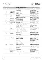
Page 184: ...e engine cool down Not enough coolant Add coolant Malfunctioning engine cooling system Check the engine cooling system and replace the malfunctioning component if necessary Malfunctioning coolant temperature sensor Replace the sensor 2 4 5 V sensor Wiring harness error Check and replace the malfunc tioning component Internal ECU error Contact an authorized workshop 2 3 Battery voltage Worn battery...

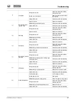
Page 185: ...ce the malfunc tioning component Malfunctioning cold starter solenoid valve Contact an authorized workshop Internal ECU error Contact an authorized workshop 1 3 Exhaust gas recircula tion valve Loose connector Tighten the connector Wiring harness error Check and replace the malfunc tioning component Malfunctioning stepping motor of exhaust gas recirculation valve Contact an authorized workshop Int...

Page 186: ...rkshop 1 6 Main relay Loose connector Tighten the connector Wiring harness error Check and replace the malfunc tioning component Malfunctioning main relay Replace the main relay Internal ECU error Contact an authorized workshop 1 2 CAN connection Battery voltage too low Charge the battery Loose connector Tighten the connector Wiring harness error Check and replace the malfunc tioning component Int...

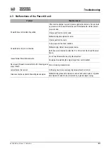
Page 187: ...valve has been installed Malfunctioning internal decompression valve Both lines are connected to either the P1 or P2 ports of the Powertilt swivel device Inexact lateral Powertilt movements Air in Powertilt swivel device or hydraulic system Hose pipe diameter length is larger longer than recommended Reverse and forward movement of shaft in housing axial play of shaft Worn or missing pressure discs...

Page 188: ...s too long or lubrication time too short Shorten breaks or increase lubrication time System clogged See Grease escapes by the pressure limit ing valve No grease rims on some lubrication points Burst or leaky supply lines to secondary distributor Replace the lines Leaky threaded fittings Retighten or replace the threaded fittings Reduced pump speed High system pressure Check system bearings Low amb...

Page 189: ...icator light 1 displays the following errors with the number of flashing pulses Fig 253 Characteristic curves status indicator 1 Number of flashing codes Error Critical error 0 No error 1 Malfunctioning input voltage channel I left hand joystick 2 Overload or overheating at output stage channel I left hand joystick 3 Short circuit on earth or operating voltage channel I left hand joystick 4 Malfun...

Page 190: ...4 12 BA 50Z3 6003 en Edition 4 3 5003b410 fm Troubleshooting ...

Page 191: ... safety glasses protective masks and clothing when using compressed air 5 2 Safety relevant parts Service and maintenance work must be performed by a specifically trained person All other maintenance work that is not indicated in this Operator s Manual must be per formed only by the trained and qualified personnel of a Wacker Neuson workshop The following maintenance plans indicate the maintenance...

Page 192: ...the risk of fire Caution Bear in mind the following important points when refuelling Avoid refuelling with cans in order to avoid dirt in the fuel When refuelling the machine without a fuel filling pump use safety oriented ladders and work platforms Never use machine parts or attachments superstructures as a climbing aid Notice Do not run the fuel tank completely dry Otherwise air is drawn into th...

Page 193: ...manner Fuel filling pump option up to serial no AD04862 Refuel with the fuel filling pump A as follows Place the machine on level ground Stop the engine Open the engine cover Insert the hose of fuel filling pump A into the container with the fuel see Stationary fuel pumps on page 5 4 Press button B to switch on fuel filling pump A The fuel tank is full as soon as indicator light C illuminates Pres...

Page 194: ... fuel pumps General If possible refuel only from stationary fuel pumps Fuel from barrels or cans is usually dirty Even the smallest particles of dirt can cause Increased engine wear Malfunctions in the fuel system and Reduced effectiveness of the fuel filters Refuelling from barrels If refuelling from barrels cannot be avoided note the following points Barrels must neither be rolled nor tilted bef...

Page 195: ...ystem may be performed only in an absolutely clean environment Bleed the fuel system only if the engine is cold Filter elements and drained fuel must be disposed of correctly Always wear protective equipment and safety glasses when working with fuel Danger Rotating parts Risk of injury Before starting the engine ensure that no one is within risk zone of the engine the machine Start the engine only...

Page 196: ...after starting the engine Have this checked by authorized personnel if necessary Fuel prefilter with water separator Draining the fuel water mixture Stop the engine Turn ball type cock B to the OFF mark Fuel supply is interrupted Check the water separator Prepare a suitable container for collecting the fuel water mixture Stop the engine Switch off ignition Remove the ignition key Raise the control...

Page 197: ...an authorized workshop see chapter 5 22 Maintenance plan overview on page 5 57 Checking the engine oil level Notice Check the oil level once a day We recommend checking it before starting the engine After stopping a warm engine wait at least 5 minutes before checking Park the machine on level and horizontal ground Stop the engine Raise the control lever base Switch off ignition Remove the ignition...

Page 198: ...it can go down without entering the intake system Environment Use a suitable container to collect the engine oil as it drains and dispose of it in an environmentally friendly manner Clean the area around oil filler cap B with a lint free cloth Open filler cap B Raise oil dipstick A slightly to allow any trapped air to escape Add engine oil Wait about 3 minutes until all the oil has run into the oi...

Page 199: ...to engine damage Therefore Check the coolant level at regular intervals Refer to the maintenance plans in the appendix for the intervals If coolant must be added frequently check the cooling system for leaks and or con tact an authorized workshop Never add cold water coolant if the engine is warm After filling the expansion tank make a test run with the engine and check the coolant level again aft...

Page 200: ...nutes after stopping the engine Wear protective gloves and clothing Open filler cap B to the first notch and release the pressure Ensure that the coolant temperature is sufficiently low so you can touch the radiator plug with your hands Danger Antifreeze is flammable and poisonous Risk of accidents Keep away from flames Avoid eye contact with antifreeze If antifreeze comes into contact with the ey...

Page 201: ...e in the radiator Carefully open the cap to the first notch and fully release the pressure Open filler cap B Add coolant up to the lower edge of the filler inlet radiator Close filler cap B Start the engine and let it warm up for about 5 10 minutes Stop the engine Remove the ignition key and carry it with you Let the engine cool down Check the coolant level again The coolant level must be between ...

Page 202: ...ills chemical plants and other nonferrous metal plants Check and if necessary replace the air filters after 50 service hours at the latest General instructions for air filter maintenance Store air filters in their original packaging and in a dry place Do not knock the air filters against other objects as you install them Check air filter attachments air intake hoses and air filters for damage and ...

Page 203: ...E ensure that it is properly seated Close bow clips D Replacing the inside air filter Remove outside air filter A as described above to access inside air filter B Carefully pull out inside air filter B Cover the air supply at the end of the filter with a clean lint free cloth to prevent dust from entering the engine Ensure that all dirt dust inside the upper and lower housing sections F and E incl...

Page 204: ...ective clothing Carefully clean the filter with compressed air Do not aim the compressed air at the skin or at other people Do not use compressed air for cleaning your clothing The machine is equipped with a cab air filter located under the seat The heater is located at the rear half of the cab Clean the cab air filter every 500 service hours and replace it every 1000 service hours Notice Raise th...

Page 205: ...ot use compressed air for cleaning your clothing If equipped with optional air conditioning the machine is fitted with a filter element located under the seat Replace the filter element every 500 service hours by a new one Notice Tilt the cab to replace the filter element see chapter 3 41 Raising lowering the cab on page 3 65 Stop the engine Remove the ignition key and carry it with you Raise the ...

Page 206: ...os Designation 1 Diesel particulate filter 5 17 2 Input cover with catalytic converter and input pipe incl flexible exhaust pipe 5 17 3 Output cover incl exhaust pipe 4 Temperature sensor 5 Pressure line 6 Pressure hose 7 Injection nozzle 5 17 8 Injection line 9 Stop cock 10 Throttle screw connection 11 Diesel lines 12 Condensate trap 5 17 13 Control box 5 17 14 Display 5 19 15 Wiring ...

Page 207: ...a catalytic converter is installed before the filter to avoid any such shortcomings Control box The control box monitors and saves the temperature and the pressure in the particulate fil ter system transmits the data to the display and controls diesel fuel injection Condensate trap The condensate trap protects the control box against damage caused by water by elimi nating the condensation water in...

Page 208: ...iculate filter system warm up the engine at low idling engine speed without load for about 15 minutes This warm up phase is of crucial importance for the 50Z3 and 6003 machines on these machines the exhaust gas recirculation valve is closed when the engine is cold which causes the exhaust gas back pressure to rise considerably Work cannot start unless the engine has reached its operating temperatu...

Page 209: ... information see Alarm messages on page 5 20 Key for alarm message acknowledgement See chapter Alarm messages for description Alarm symbol This symbol flashes in case of an alarm This symbol goes out as soon as an error is acknowledged 1 2 3 4 5 6 7 8 F psi C mbar Temperature Pressure Druck Alarm Alarm symbol Temperature Exhaust gas back pressure Alarm code Key for alarm message acknowledgement Fi...

Page 210: ...display and controls Troubleshooting Contact an authorized workshop Indication Pressure LED 1 alarm LED 2 and alarm symbol flash Error Lower limit of exhaust gas counterpressure exceeded Troubleshooting Check pressure hose and line for leaks Check particulate filter and input pipe for leaks Contact an authorized workshop Indication Pressure LED 1 alarm LED 4 and alarm symbol flash Error No pressur...

Page 211: ...ly operate the machine in a way that puts a high load on the engine in order to regenerate the filter If the pressure does not fall after 5 minutes stop the engine and get in touch with an authorized workshop Indication Alarm LED 3 and the alarm symbol flash Error No engine speed signal from the alternator Troubleshooting Wiring from controls to alternator Check the wiring Contact an authorized wo...

Page 212: ...bol flash Error Error in controls program Troubleshooting Contact an authorized workshop Indication Alarm LED 5 and the alarm symbol flash Error Error in controls program Troubleshooting Contact an authorized workshop Indication Alarm LEDs 4 to 8 and the alarm symbol flash Error Dirty display glass Troubleshooting Clean the display glass 1 2 3 4 5 6 7 8 Fig 281 Error programming 1 2 3 4 5 6 7 8 Fi...

Page 213: ...ust manifold for tightness Ensure that there is no soot on the end pipe of the particulate filter Once a year every 500 h Have the system components checked for correct function by an authorized service Contact an authorized workshop Statutory maintenance work Get in touch with an authorized workshop for information on possible country specific statutory maintenance work As required If the maximum...

Page 214: ...ust gas is caused by evaporating water or unburnt diesel fuel When starting a cold engine normally emits white smoke briefly when the condensation water in the partic ulate filter evaporates On a warm engine white exhaust gas is caused by unburnt diesel fuel of the active diesel fuel injection during active regeneration and should disappear again after a short time Get in touch with an authorized ...

Page 215: ...ontrol lever base Remove the ignition key and carry it with you Disconnect the battery or actuate the battery master switch Let the engine cool down Open the engine cover Carefully check V belt 1 for damage cracks or cuts If the V belt is damaged Have the V belt replaced by authorized personnel Replace the V belt if it touches the base of the V belt groove or if the pulleys are damaged Press with ...

Page 216: ...ngine Raise the control lever base Remove the ignition key and carry it with you Disconnect the battery or actuate the battery master switch Let the engine cool down Open the engine cover Slacken fastening screws 3 of alternator 4 Use a suitable tool to push the alternator in the direction of arrow A until reaching the correct V belt tensionFig 288 Keep the alternator in this position and at the s...

Page 217: ... thumb about 100 N 22 5 lbf to check the deflection of the V belt between the pulley and the crankshaft disc A new V belt should have a deflection of 7 to 9 mm 0 27 to 0 35 in a used V belt after about 5 minutes running time should have a deflection of 9 to 11 mm 0 35 to 0 43 in Retighten the V belt if necessary Connect the battery or the battery master switch Close and lock the engine cover Tight...

Page 218: ...following problems is detected Damaged or leaky hydraulic seals Worn or torn shells or uncovered reinforcement branches Expanded shells in several positions Entangled or crushed movable parts Foreign bodies jammed or stuck in protective layers Caution Dirty hydraulic oil lack of oil or wrong hydraulic oil Danger of severe damage to the hydraulic system Take care to avoid dirt when working Always a...

Page 219: ...ne cover Sight glass B is located at the rear right corner of the machine on hydraulic oil tank A Check the oil level on sight glass B The oil level must be about 1 cm 0 39 in over the centre between positions MIN and MAX as shown by the arrows in Fig 292 The MIN mark is black The MAX mark is yellow If the oil level is lower Add hydraulic oil Close and lock the engine cover The oil level varies ac...

Page 220: ...r the boom and the bucket teeth to the ground Lower the stabilizer blade to the ground Set the boom straight slewing ram Stop the engine Raise the control lever base Remove tank cover V Open breather filter A carefully to release the pressure inside the tank Slowly open plug C with tool D included in the tool kit With the filter insert in place Add hydraulic oil Check the hydraulic oil level on si...

Page 221: ...es Therefore ensure that the remaining amount of initial hydraulic fluid in the hydraulic system does not exceed 8 when changing biodegradable oil manufacturer indications Do not add mineral oil the content of mineral oil should not exceed 2 in order to avoid foaming problems and to ensure biological degradability When running the machine with biodegradable oil the same oil and filter replacement ...

Page 222: ...are hands but wear protective gloves Use paper or wood to check for minor leaks Never use an unprotected light or naked flame Have damaged flexible lines replaced by authorized workshops only Leaks and damaged pressure lines must be immediately repaired or replaced by an authorized workshop This not only increases the operating safety of the machine but also helps to protect the environment Replac...

Page 223: ...hine on firm level and horizontal ground Raise the machine evenly and horizontally by means of the boom and the stabilizer blade Slowly and carefully actuate the control levers The rubber track has a mark B as shown in Fig 295 Place the machine so that mark B of the rubber track is between the drive pinion C and the track tension roller D Stop the engine Raise the control lever base Remove the ign...

Page 224: ...acken no other component except the lubricating valve Keep your face away from the lubricating valve connection Contact an authorized workshop if this does not reduce track tension Release grease only as described below Observe the safety instructions Caution Excessive tension of the tracks causes severe damage to the ram and the track Tighten the tracks only up to the prescribed measuring distanc...

Page 225: ...he lubricating valve A Check the tension is correct by lowering the machine to the ground starting the engine letting it run at idling speed without any load and slowly moving the machine forward and reverse and switching it off again Lift the machine again Check the tension of the tracks again If the tension is not correct Adjust again Environment Use a suitable container to collect the grease as...

Page 226: ...B with a suitable tool A small quantity of oil must flow out of opening B If the oil does not flow out of opening B add oil Add oil through opening A until a small quantity of oil flows out of opening B Screw screws A and B back in again Move the machine a few metres Check the oil level again If the oil level is not correct Repeat the procedure Draining oil Place the machine on firm level and hori...

Page 227: ...nents Cables lamps and fuses Always observe the following instructions Malfunctioning components of the electrical system must always be replaced by an authorized expert Bulbs and fuses may be changed by the user When performing maintenance work on the electrical system pay particular attention to ensuring good contact in leads and fuses Blown fuses indicate overloading or short circuits The elect...

Page 228: ...en mixture is formed in the battery cells Explosion hazard Avoid naked lights and sparks in the vicinity of the battery and do not smoke Do not attempt to jump start the machine if the battery is frozen or if the acid level is low The battery can rupture or explode Replace the battery immediately Always disconnect the negative terminal from the battery before starting repair work on the electrical...

Page 229: ...g direction The battery is maintenance free However have the battery checked at regular intervals to ensure that the electrolyte level is between the MIN and MAX marks Checking the battery requires it to be removed and must be performed by an authorized workshop Always follow the specific battery safety instructions Fig 302 Battery A ...

Page 230: ...tective clothing Do not aim the compressed air at the skin or at other people Do not use compressed air for cleaning your clothing Cleaning with a high pressure cleaner or steam jet Cover electric parts Do not directly expose electrical components and damping material to the jet Cover the vent filter on the hydraulic oil tank and the filler caps for fuel hydraulic oil etc Protect the following com...

Page 231: ...ne with a water or steam jet The engine must be cold and do not point the jet directly at electric sensors such as the oil pressure switch The humidity penetrating any such sensors causes them to fail and leads to engine damage Threaded fittings and attachments All threaded fittings must be checked regularly for tightness even if they are not listed in the maintenance schedules Engine fastening sc...

Page 232: ...5 42 BA 50Z3 6003 en Edition 4 3 5003b530 fm Maintenance 5 17 Overview of lubrication points 8 8 1 4 2 1 14 7 2 3 4 5 5 Triple articulation boom 6003 option Stabilizer blade 6 13 12 11 10 10 10 10 10 ...

Page 233: ...ver Perform maintenance work Notice Keep the lubrication points clean and remove ejected grease Lubrication points on the boom bucket and stick rams Apply grease to lubrication points 1 on the bucket ram Pos Lubrication point Interval Quan tity 1 Bucket ram Daily 2 2 Stick ram Daily 2 3 Boom ram Daily 2 4 Boom Daily 2 5 Stick Daily 2 6 Joint rod Daily 1 7 Stabilizer blade ram Daily 2 8 Stabilizer ...

Page 234: ...2 on the stick ram Apply grease to lubrication points 3 on the boom ram Apply grease to lubrication points 3 on the boom ram Lubrication points on the boom and stick Apply grease to lubrication points 4 on the boom Fig 305 Lubrication points on bucket and stick rams 2 1 Fig 306 Lubrication points on boom and stick rams 2 3 Fig 307 Lubrication points on the boom ram 3 Fig 308 Boom lubrication point...

Page 235: ...on points on the stabilizer blade and stabilizer blade ram Apply grease to lubrication points 7 on the stabilizer blade ram Apply grease to lubrication points 8 on either side on the stabilizer blade Apply grease to lubrication points 9 on the stabilizer blade ram Fig 309 Boom lubrication points 4 Fig 310 Lubrication points on the stick 5 Fig 311 Lubrication points on the stick 5 Fig 312 Lubricati...

Page 236: ...e Apply grease to lubrication points 11 on the slewing ram Apply grease to lubrication point 11 of the offset ram Apply grease to lubrication points 12 of the swivelling console Fig 314 Lubrication point on slewing ram 11 Fig 315 Lubrication point on slewing ram 11 Fig 316 Lubrication points on swivelling console 12 ...

Page 237: ...Parking the machine on page 5 43 Stop and park the machine Apply grease to lubrication points 13 with one stroke of the grease gun Remove ejected grease Turn the machine 90 at a time Stop and park the machine Apply grease to each of lubrication points 13 with one stroke of the grease gun Remove ejected grease Turn the machine 360 a few times Fig 317 Lubrication points of ball bearing race 13 Fig 3...

Page 238: ...ing the machine on page 5 43 Caution Lubrication can be performed over a pit only Drive and stop the machine over a pit The lubrication point is located on the lower side of the travel gear Remove cover A on the lower side with a suitable tool Apply grease to lubrication point 14 with five strokes of the grease gun Remove ejected grease Install the cover Fig 319 Removing the cover A Fig 320 Teeth ...

Page 239: ...ver must ensure that it can be hitched cor rectly by removing all dirt on either claw of the quickhitch Perform maintenance on the quickhitch once a day with the other maintenance work for the machine Perform visual checks for possible defects damage or cracks Remove all dirt on and around moving parts The claws must be clean and slightly greased Apply grease to the friction surfaces of the lock m...

Page 240: ...rease on both sides of double spring D Notice Spray fluid grease onto the lubrication points once a month 250 s h Danger In the area of the moving parts of the control lever base Crushing hazard Stay clear extremities clothing of the moving parts VDS lubrication points option Apply grease to lubrication points A once a week Fig 323 Guide lever and double spring C D Fig 324 VDS lubrication points A...

Page 241: ...cording to the cycle time set Lubrication time is stopped and saved if ignition or lubrication is switched off during cycle time The data is read from the memory upon switching ignition on again and lubrication is resumed where it was interrupted Pressing the push button on the motor housing or on the instrument panel starts intermedi ate lubrication if ignition is switched on Status LEDs 4 1 5 3 ...

Page 242: ... off the main distributor Actuate the pump with the push button and check whether the lubricant is delivered correctly Screw the main line onto the main distributor Unscrew the lines one after another and actuate the pump every time Repairing a clogged distributor Remove the distributor from the system Unscrew the screw plug of the piston bore Move the piston back and forth do not remove Screw the...

Page 243: ...ine is out of service for a longer period of time The following measures must be taken if the machine is out of service for more than 30 days Putting into operation again Remove anticorrosion agent from the piston rods Charge install and connect the battery Remove the seals from the exhaust pipe and the air filter intake Check the condition of the air filter element and replace the element if nece...

Page 244: ...1524 section 3 HVLP HEES HLP Synth 46 BIOHYD SE S 46 Grease Roller and friction bear ings KPF 2 K 209 ISO L X BCEB 210 9 KPF 2 K 20 according to DIN 51502 multipurpose lithium grease 10 ISO L X BCEB 2 according to DIN ISO 6743 9 Grease As required Open transmissions live ring ball bearing Live ring gears Grease nipples Grease nipples Multipurpose grease KPF 2 K 2011 11 KPF 2 K 20 according to DIN ...

Page 245: ...llowing intervals Notice Please refer to the maintenance plan on page 5 57 for additional maintenance work Engine oil grade Ambient temperature C API CF CF 4 CI 4 ACEA E3 E4 E5 JASO DH 1 C 20 15 10 5 0 5 10 15 20 25 30 35 40 SAE 10W SAE 20W SAE 10W 40 SAE 15W 40 SAE 20 SAE 30 SAE 40 F 4 5 14 23 32 41 50 59 68 77 86 95 104 Application Hydraulic oil Hydraulic oil filter insert Normal work excavation...

Page 246: ...raulic system depending on temperature Hydrau lics oil grade Ambient temperature HVLP 46 1 HV 46 2 C 20 15 10 5 0 5 10 15 20 25 30 35 40 50 ISO VG32 ISO VG46 ISO VG68 F 4 5 14 23 32 41 50 59 68 77 86 95 104 122 1 According to DIN 51524 section 3 ISO VG 46 2 According to ISO 6743 4 ...

Page 247: ...anges Perform the following oil and filter changes check oil levels after test run Engine oil 1 Engine oil filter 2 Fuel filter 3 Air filter element as indicated by indicator light 4 Coolant Hydraulic oil filter insert 5 Hydraulic oil Hydraulic oil tank breather Drain the condensation water from the hydraulic oil tank Replace cab air filter for heating and air conditioning Drive gearbox oil 6 Insp...

Page 248: ...sion Replacing the V belt Check the exhaust system for damage and condition Check valve clearance Adjust if necessary Lapping the intake and exhaust valves Check and adjust the injection pressure of the injection nozzles clean the injection needles nozzles Empty the fuel tank and check for dirt Check battery electrolyte Add distilled water if necessary Check alternator starter and electric connect...

Page 249: ...mpleteness and condition Adjust the mirrors option correctly clean them and check them for damage and correct function Check all fastening screws on the mirrors option and tighten them if necessary Check function of engine cover gas strut Check hydraulic quickhitch for damage Lights and acoustic warning system 8 Check gearing of swivel unit pinion Check Powertilt option for damage Check the axial ...

Page 250: ...rol lever base Air conditioning Perform the following maintenance and inspection work Air conditioning function 12 Change the cab air filter Check dehumidifier for corrosion condensation and air bubbles Replace dehumidifier Compressor oil 13 Functional check Check the function of the following assemblies components Rectify if necessary Lights signalling system acoustic warning system 5 22 Maintena...

Page 251: ... extensive use in environments with acidic air such as acid production facilities steel and aluminium mills chemical plants and other nonferrous metal plants 5 Replace the hydraulic oil filter insert the first time after 50 s h then every 500 s h 6 Drain the gearbox oil the first time after 50 s h then every 1000 s h 7 Check the first time after 50 s h then every 500 s h 8 Check once a week 9 Chec...

Page 252: ...efilter Radiator Check the coolant level Radiator Drain and add new coolant Engine Check valve clearance Adjust if necessary Engine Check the engine oil level Engine Change the engine oil Engine Replace the oil filter Engine Check V belt tension Travelling drive Change oil Travelling drive Check oil Travel gear Check track tension Hydraulic system Check oil level Hydraulic system Change the hydrau...

Page 253: ...BA 50Z3 6003 en Edition 4 3 5003b560 fm 5 63 Symbol Assembly Explanation Radiator fins Clean Heating air conditioning Replace the recirculated air filter ...

Page 254: ...5 64 BA 50Z3 6003 en Edition 4 3 5003b560 fm ...

Page 255: ... and stroke 88 x 90 mm 3 46 x 3 54 in 88 x 90 mm 3 46 x 3 54 in 98 x 110 mm 3 85 x 4 3 in 98 x 110 mm 3 85 x 4 3 in Output 28 2 kW 37 8 hp at 2400 rpm 28 6 kW 38 3 hp at 2400 rpm 43 4 kW 58 2 hp at 2100 rpm 43 4 kW 58 2 hp at 2100 rpm Max torque 138 3 Nm 102 lbf ft at 1100 rpm 142 3 Nm 104 9 lbf ft at 1350 rpm 238 3 Nm 175 8 ft lbs at 1350 rpm 238 3 Nm 175 8 ft lbs at 1350 rpm Max engine speed wit...

Page 256: ... control circuit 11 sections 12 sections 3rd control circuit 13 sections triple articulation boom control Max operating pressure 230 5 bar 3336 72 psi 240 5 bar 3481 72 psi Main pressure restriction for boom bucket stick 230 5 bar 3336 72 psi 240 3 bar 3481 72 psi Main pressure restriction for stabilizer blade 230 3 bar 3336 72 psi 240 3 bar 3481 72 psi Main pressure restriction for pilot control ...

Page 257: ...ent A Protected circuit F3 10 A Indicators cutoff solenoid relays F4 10 A Boom light F5 15 A Roof lights F6 10 A Valves horn F7 15 A Heating air conditioning F8 10 A Wiper interior light F9 10 A Rotating beacon radio drive interlock F10 15 A Socket cigarette lighter Fig 326 Fuse box from serial no AJ02777 F3 F4 F8 F9 F10 F5 F6 F7 Fig 327 Relay box under the cab K9 K5 F1 F2 Fuse no Rated current A ...

Page 258: ...circuit K 6 Preheating timer K 7 Starting relay K 8 Cutoff solenoid timer V 1 Diode Electrical system Alternator 12 V 55 A Starter 12 V 3 0 kW Battery 12 V 88 Ah Socket For cigarette lighter for example 15 A max Fig 329 Fuse box F3 F4 F5 F6 F7 F8 F9 F10 Fuse no Rated current A Protected circuit F3 10 A Displays E ECU F4 10 A Boom working light F5 15 A Cab working light F6 10 A Valves horn F7 15 A ...

Page 259: ...ng pump main fuse ignition lock F11 10 A E ECU engine relays Relay no K1 Engine electronics main relay K2 Fuel filling pump relay K5 Preheating high current relay K7 Start high current relay K42 Fuel injection pump relay V1 Blocking diode Fig 331 Fuse box F3 F4 F5 F6 F7 F8 F9 F10 Fuse no Rated current A Protected circuit F3 10 A Displays E ECU F4 10 A Boom working light F5 15 A Cab working light F...

Page 260: ... risks arising from physical agents vibra tion Indications on hand arm vibration Hand arm vibration is less than 2 5 m s during correct machine operation Indications on whole body vibration Whole body vibration is less than 0 5 m s during correct machine operation Uncertainty of measurement K has been taken into account for the specified values Fig 332 ECU control unit Sound power level Model 50Z ...

Page 261: ...n earth moving machines For more information on the vibration values of the machine refer to Directive 2002 44 EC of European Parliament and Coucil on minimum health and safety requirements regarding exposure of workers to risks arising from physical agents vibra tion It explains the values for vertical vibration under heavy operating conditions Directives on reduction of vibration values in earth...

Page 262: ...inimum Reference The vibration values and calculations are based on the indications made in ISO TR 25398 Mechanical Vibrations Guidelines for assessment of exposure to whole body vibration when operating earth moving machines The harmonized data comply with measurements made by international institutes organi zations and manufacturers This publication offers information on the calculation of whole...

Page 263: ... tempera ture Coolant Water Anticorrosion agent Antifreeze agent Up to C F by volume cm l in3 gal by volume by volume 37 34 6 50 10 2 6 1 50 Powertilt Models 50Z3 6003 Model size 7 Piston stroke 1060 cm 64 7 in Required oil flow 6 12 l min 1 6 3 2 gal min Ports 1 4 Swivelling range 180 1 1 The actual angle can vary slightly from the indication made here Weight 115 kg 253 5 lbs Drive torque at 210 ...

Page 264: ... 936 lbs Operating weight 2 2 Service weight basic machine full fuel tank backhoe bucket 700 mm user 75 kg 165 lbs With canopy 5180 kg 11 420 lbs 5565 kg 12 269 lbs With cab 5302 kg 11 689 lbs 5687 kg 12 538 lbs Weight 6003 6003 Vario Transport weight1 1 Transport weight basic machine 10 fuel capacity With standard boom 5607 kg 12 361 lbs 6072 kg 13 386 lbs With triple articulation boom 5882 kg 12...

Page 265: ...BA 50Z3 6003 en Edition 4 3 5003b610 fm 6 11 Specifications 6 16 Dimensions model 50Z3 ...

Page 266: ... long stick 6225 mm 20 5 N Max reach at ground level short stick 5860 mm 19 3 O Max reach at ground level long stick 6105 mm 20 0 P Min tail end swivelling radius 995 mm 39 in Q Max boom displacement to bucket centre right side 960 mm 38 in R Max boom displacement to bucket centre left side 895 mm 35 in S Max lift height of stabilizer blade over ground 415 mm 16 in T Max scraping depth of stabiliz...

Page 267: ...BA 50Z3 6003 en Edition 4 3 5003b610 fm 6 13 Specifications 6 17 Dimensions model 50Z3 VDS ...

Page 268: ...k 6225 mm 20 5 N Max reach at ground level short stick 5820 mm 19 1 O Max reach at ground level long stick 6070 mm 19 11 P Min tail end swivelling radius 995 mm 39 in Q Max boom displacement to bucket centre right side 960 mm 38 in R Max boom displacement to bucket centre left side 895 mm 35 in S Max lift height of stabilizer blade over ground 415 mm 16 in T Max scraping depth of stabilizer blade ...

Page 269: ...BA 50Z3 6003 en Edition 4 3 5003b610 fm 6 15 Specifications 6 18 Dimensions model 6003 standard boom Vario option ...

Page 270: ... Max reach at ground level short stick 6122 mm 20 1 63451 68452 mm 20 10 22 5 O Max reach at ground level long stick 6415 mm 21 1 66401 71402 mm 21 9 23 5 P Min tail end swivelling radius 1465 mm 58 in 1465 mm 58 in Q Max boom displacement to bucket centre right side 745 mm 29 in 745 mm 29 in R Max boom displacement to bucket centre left side 535 mm 21 in 535 mm 21 in S Max lift height of stabiliz...

Page 271: ...BA 50Z3 6003 en Edition 4 3 5003b610 fm 6 17 Specifications 6 19 Dimensions model 6003 triple articulation boom option ...

Page 272: ... digging radius long stick 6894 mm 22 7 N Max reach at ground level short stick 6495 mm 21 4 O Max reach at ground level long stick 6790 mm 22 3 P Min tail end swivelling radius 1465 mm 58 in Q Max boom displacement to bucket centre right side 745 mm 29 in R Max boom displacement to bucket centre left side 535 mm 21 in S Max lift height of stabilizer blade over ground 390 mm 15 in T Max scraping d...

Page 273: ...0 78 7 in A B Lowered blade Lowered blade Lowered blade Lowered blade 4 0 m 13 1 1060 2337 810 1785 3 0 m 9 10 1025 2260 585 1290 1010 2227 780 1720 2 0 78 7 in 1045 2304 490 1080 1185 2612 730 1609 1580 3483 1150 2535 1 0 39 4 in 1090 2403 455 1003 1415 3119 670 1477 2225 4905 990 2183 0 0 m 0 0 in 1145 2524 460 1014 1555 3428 625 1378 2435 5368 920 2028 1 0 m 39 4 in 1210 2668 515 1135 1510 3329...

Page 274: ... 9 10 2 0 78 7 in A B Lowered blade Lowered blade Lowered blade Lowered blade 4 0 m 13 1 1060 2337 915 2017 3 0 m 9 10 1025 2260 675 1488 1010 2227 910 2006 2 0 78 7 in 1045 2304 580 1279 1185 2612 865 1907 1580 3483 1345 2965 1 0 39 4 in 1090 2403 545 1201 1415 3119 805 1775 2225 4905 1185 2612 0 0 m 0 0 in 1145 2524 550 1212 1555 3428 760 1675 2435 5368 1115 2458 1 0 m 39 4 in 1210 2668 620 1367...

Page 275: ...in A B Lowered blade Lowered blade Lowered blade Lowered blade 4 0 m 13 1 920 2028 660 1455 855 1885 785 1731 3 0 m 9 10 915 2017 500 1102 865 1907 780 1720 2 0 78 7 in 935 2062 425 937 1050 2315 730 1610 1315 2900 1170 2580 1 0 39 4 in 970 2139 395 871 1310 2889 665 1466 2025 4465 1010 2227 0 0 m 0 0 in 1015 2238 400 882 1495 3297 610 1345 2385 5259 915 2018 1 0 m 39 4 in 1065 2348 440 970 1515 3...

Page 276: ...8 7 in A B Lowered blade Lowered blade Lowered blade Lowered blade 4 0 m 13 1 920 2028 780 1720 855 1885 855 1885 3 0 m 9 10 915 2017 600 1323 865 1907 865 1907 2 0 78 7 in 935 2062 520 1147 1050 2315 865 1907 1315 2900 1315 2900 1 0 39 4 in 970 2139 485 1069 1310 2889 800 1764 2025 4465 1205 2657 0 0 m 0 0 in 1015 2238 490 1080 1495 3297 745 1643 2385 5259 1110 2448 1 0 m 39 4 in 1065 2348 540 11...

Page 277: ...ed blade Lowered blade Raised blade 3 0 m 9 10 1018 2245 617 1360 683 1506 965 2128 829 1828 921 2031 2 0 m 78 7 in 1049 2313 537 1184 594 1310 1048 2311 552 1217 612 1349 1155 2547 791 1744 881 1942 1501 3310 1233 2718 1398 3082 1 0 m 39 4 in 1095 2414 511 1127 566 1248 1122 2474 535 1179 594 1309 1406 3100 743 1638 831 1832 2196 4841 1114 2456 1271 2802 0 0 m 0 0 in 1153 2542 528 1164 587 1294 1...

Page 278: ...de Raised blade Lowered blade Raised blade 3 0 m 9 10 1018 2245 669 1475 744 1640 965 2128 894 1971 965 2128 2 0 78 7 in 1049 2313 585 1290 650 1433 1048 2311 601 1325 669 1475 1155 2547 856 1887 957 2110 1501 3310 1328 2928 1501 3310 1 0 m 39 4 in 1095 2414 558 1230 621 1369 1122 2474 584 1288 651 1435 1406 3100 808 1782 907 2000 2196 4841 1209 2666 1384 3052 0 0 m 0 0 in 1153 2542 577 1272 644 1...

Page 279: ...sed blade 3 0 m 9 10 929 2048 555 1224 615 1356 929 2048 555 1224 615 1356 843 1859 829 1828 843 1859 2 0 78 7 in 960 2117 486 1072 540 1191 961 2119 545 1202 605 1334 1043 2300 787 1735 878 1936 1275 2811 1246 2747 1275 2811 1 0 m 39 4 in 1005 2216 463 1021 515 1136 1060 2337 522 1151 582 1283 1315 2900 733 1616 821 1810 2017 4447 1112 2452 1270 2800 0 0 m 0 0 in 1060 2337 475 1047 530 1169 1127 ...

Page 280: ...ade Raised blade 3 0 m 9 10 929 2048 604 1332 672 1482 929 2048 604 1332 672 1482 843 1859 843 1859 843 1859 2 0 78 7 in 960 2117 532 1173 593 1308 961 2119 594 1310 662 1460 1043 2300 852 1879 954 2104 1275 2811 1275 2811 1275 2811 1 0 m 39 4 in 1005 2216 508 1120 567 1250 1060 2337 572 1261 639 1409 1315 2900 798 1760 897 1978 2017 4447 1207 2661 1384 3051 0 0 m 0 0 in 1060 2337 522 1151 584 128...

Page 281: ...wered blade Lowered blade Lowered blade 4 0 m 13 1 1310 2889 1020 2249 1245 2745 1155 2547 3 0 m 9 10 1300 2867 805 1775 1265 2789 1145 2525 2 0 78 7 in 1320 2911 710 1566 1330 2933 775 1709 1490 3285 1100 2425 1885 4156 1700 3748 1 0 39 4 in 1360 2999 675 1488 1435 3164 750 1654 1775 2591 1035 2282 2615 5766 1550 3418 0 0 m 0 in 1410 3109 690 1521 1495 3296 730 1610 1970 4333 990 2183 2970 6549 1...

Page 282: ... blade Lowered blade Lowered blade Lowered blade 4 0 m 13 1 1310 2889 1175 2591 1245 2745 1245 2745 3 0 m 9 10 1300 2867 935 2062 1265 2789 1265 2789 2 0 78 7 in 1320 2911 830 1830 1330 2933 905 1995 1490 3285 1265 2789 1885 4156 1885 4156 1 0 39 4 in 1360 2999 795 1753 1435 3164 880 1940 1775 2591 1205 2657 2615 5766 1795 3958 0 0 m 0 in 1410 3109 810 1786 1495 3296 850 1874 1970 4333 1155 2547 2...

Page 283: ...d blade Lowered blade Lowered blade Lowered blade 4 0 m 13 1 1190 2624 990 2183 1050 2315 865 1907 3 0 m 9 10 1190 2624 640 1411 1120 2469 1055 2326 2 0 78 7 in 1220 2690 285 628 1245 2745 715 1577 1375 3032 1085 2392 1670 3682 1670 3685 1 0 39 4 in 1265 2789 530 1169 1380 3043 725 1599 1690 3726 1030 2271 2400 5292 1570 3462 0 0 m 0 in 1315 2900 585 1290 1485 3274 705 1554 1925 4245 980 2161 2805...

Page 284: ...owered blade Lowered blade Lowered blade Lowered blade 4 0 m 13 1 1190 2624 1130 2492 1050 2315 1035 2282 3 0 m 9 10 1190 2624 760 1676 1120 2469 1120 2469 2 0 78 7 in 1220 2690 395 871 1245 2745 845 1863 1375 3032 1250 2756 1670 3682 1670 3682 1 0 39 4 in 1265 2789 640 1411 1380 3043 850 1874 1690 3726 1200 2646 2400 5292 1815 4002 0 0 m 0 in 1315 2900 700 1543 1485 3274 835 1841 1925 4245 1145 2...

Page 285: ...e Lowered blade 5 0 m 16 5 1335 2944 1005 2216 4 0 m 13 1 1180 2602 710 1566 1175 2591 745 1643 1225 2701 1150 2536 3 0 m 9 10 1120 2470 580 1279 1175 2591 745 1643 1330 2933 1105 2436 2 0 78 7 in 1090 2403 515 1136 1255 2767 705 1554 1540 3396 1020 2249 2110 4653 1610 3550 1 0 39 4 in 1070 2359 485 1069 1340 2955 660 1455 1740 3837 925 2040 2540 5601 1380 3043 0 0 m 0 0 in 1050 2315 485 1069 1370...

Page 286: ...d blade Lowered blade 5 0 m 16 5 1335 2944 1160 2558 4 0 m 13 1 1180 2602 830 1830 1175 2591 875 1929 1225 2701 1225 2701 3 0 m 9 10 1120 2470 690 1521 1175 2591 870 1918 1330 2933 1275 2811 2 0 78 7 in 1090 2403 615 1356 1255 2767 835 1841 1540 3396 1190 2624 2110 4653 1855 4090 1 0 39 4 in 1070 2359 585 1290 1340 2955 785 1731 1740 3837 1090 2403 2540 5601 1625 3583 0 0 m 0 0 in 1050 2315 590 13...

Page 287: ...blade Lowered blade 5 0 m 16 5 1510 3330 1220 2690 4 0 m 13 1 1300 2866 805 1775 1335 2944 1125 2481 3 0 m 9 10 1220 2690 640 1411 1250 2756 735 1621 1415 3120 1090 2403 2 0 78 7 in 1180 2602 565 1246 1300 2866 705 1554 1600 3528 1010 2227 2265 4994 1555 3429 1 0 39 4 in 1155 2547 535 1180 1365 3010 665 1466 1785 3936 920 2029 2710 5976 1350 2977 0 0 m 0 0 in 1125 2481 540 1191 1365 3010 630 1389 ...

Page 288: ...ered blade Lowered blade 5 0 m 16 5 1510 3330 1400 3087 4 0 m 13 1 1300 2866 940 2073 1335 2944 1295 2855 3 0 m 9 10 1220 2690 760 1676 1250 2756 860 1896 1415 3120 1255 2767 2 0 78 7 in 1180 2602 675 1488 1300 2866 830 1830 1600 3528 1175 2591 2265 4994 1800 3969 1 0 39 4 in 1155 2547 640 1411 1365 3010 790 1742 1785 3936 1085 2392 2710 5976 1595 3517 0 0 m 0 0 in 1125 2481 650 1433 1365 3010 760...

Page 289: ... 1105 2436 615 1356 1265 2789 1265 2789 880 1940 2 0 m 78 7 in 1320 2911 975 2150 545 1202 1330 2933 1060 2337 595 1312 1490 3285 1490 3285 845 1863 1885 4156 1885 4156 1305 2877 1 0 m 39 4 in 1360 2999 925 2040 520 1147 1435 3164 1030 2271 575 1268 1775 3914 1420 3131 795 1753 2615 5766 2125 4686 1190 2624 0 0 m 0 in 1410 3109 945 2083 530 1169 1495 3296 1000 2205 560 1235 1970 4344 1355 2988 760...

Page 290: ...hich it can perform a 360 rotation with the upper carriage without tipping over If an attachment hydraulic quickhitch or Powertilt console is installed the weight of the attachment must be subtracted from the value that has been determined before Exchangeable equipment backhoe bucket grab hammer for example installed on the boom must be removed before a lifting gear application Example for determi...

Page 291: ...hich have already been delivered and which will not be implemented on these machines Technical data dimensions and weights are given as an indication only Responsibility for errors or omissions not accepted No reproduction or translation of this publication in whole or part without the written con sent of Wacker Neuson Linz GmbH All rights under the provision of the Copyright Act are reserved Wack...

Page 292: ...Wacker Neuson Linz GmbH Flughafenstr 7 A 4063 Hörsching Phone 43 0 7221 63000 Fax 43 0 7221 63000 2200 E mail office linz wackerneuson com www wackerneuson com Order no 1000127717 Language en ...

Reviews: