


Page 13 of 48
PAM-199-P
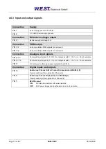
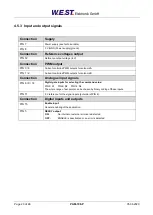
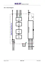
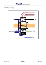
4.3.3 Input and output signals
Connection
Supply
PIN 7
Power supply (see technical data)
PIN 8
0 V (GND) Power supply (ground).
Connection
Reference voltages output
PIN 12
Reference output voltage (8 V).
Connection
PWM output
PIN 3 / 4
Current controlled PWM outputs for solenoid A.
PIN 1 / 2
Current controlled PWM outputs for solenoid B.
Connection
Analogue input signals
PIN 9 / 10
Command signal (W), range -
100…100 % corresponds with -10…10 V or 4…20 mA, scalable.
PIN 11
0 V reference for the signal inputs (potential from PIN 8).
Connection
Digital inputs and outputs
PIN 15
Enable Input
:
General enabling of the application.
PIN 6
S1 input:
Function depends on parameter
PIN:6
(USCALE/RAMP).
OFF:
Output current depends on parameter USCALE; ramp function is deactivated.
ON:
Output current is not scaled by USCALE, ramp function is activated.
PIN 5
READY output
:
ON:
Module is ready, no errors are detected
OFF:
ENABLE is deactivated or an error is detected.