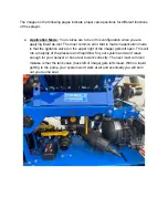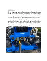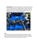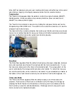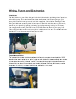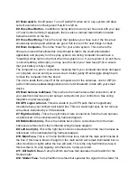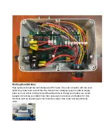
#1: Main switch-
On/off power. Turn off ALWAYS when not in use, system will draw
current even when not being used if switch is left on
#2: Hose Reel Button-
In addition to being able to rewind your hose reel with your app
or Total Control remote (if equipped), there is also a manual rewind button located
below the switch on the box.
#3: Hose Reel Relay-
This is the relay that operates your hose reel, if the hose reel
should stop working and all fuses are good, this is one of the next things to check.
#4:
Main Computer-
This is the “brain” for your entire system. This is where the
firmware is stored that allows this circuit board to talk to the smart phone/tablet
application and properly run the spray system. A working computer should have a
“breathing” white light on the front when the system is on. If your system is on and there
is not a breathing white light, you may need to check your main fuse (#10) or ensure
that your battery is fully charged.
The computer is a pin on connection, meaning that if your computer becomes damaged
or corrupted, we can send you a new one to install, gently lift and wiggle straight up to
remove the computer from the board.
The 2 wire leads that come off of the computer are for the antennas, one for WiFi (to
perform firmware updates/diagnostics) and one for Bluetooth to talk with your smart
device.
#5:
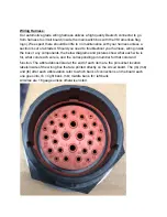
Main harness bulkhead-
This is where the main harness that connects to all of
your electronic devices on your sprayer connects into your control box. See wiring
diagrams on previous pages
#6: GPS signal wire out-
This wire leads to your GPS puck that is magnetically
mounted above your wiring/circuit board box. This is a water tight seal, do not remove
wire unless instructed by a VSI associate.
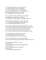
#7: Right bank (rb)-
This is the right bank of wire connections from the main harness
as referenced in the numbered wiring harness diagram.
#8: Middle Bank (mb)-
This is the middle bank of wire connections from the main
harness as referenced in the numbered wiring harness diagram.
#9: Left bank (lb)-
This is the right bank of wire connections from the main harness as
referenced in the numbered wiring harness diagram.
#10: Main Fuse-
This is a 10 amp 5x20mm bus fuse, behind the main switch inside of
the box. If this fuse is blown, the light on the main switch will remain illuminated but no
other functions or lights within the box will work. This is the only 5x20mm bus fuse in
this box that is 10 amp capacity. All others are 5 amp, as noted.
#11: Kill Switch Fuse-
5 amp 5x20mm bus fuse that operates the kill switch for the
Honda motor.
#12: Starter Fuse-
5 amp 5x20mm bus fuse that operates the signal for the starter for

