


LSI user guide
Operation
The LSI is a handy accessory that logs, synchronizes, and interfaces with any CAN bus equipped VR LRU.
VR Avionics line-replaceable units (LRU's) constantly send out detailed operational information over CAN
bus, and the LSI is able to capture and log all of it to memory card – a micro SD card in this case. This
card can be left in the LSI without much worry of running out of memory, and should something of
interest have occurred during a passed flight, the card can then be extracted and the log file
conveniently inspected on a PC.
Additional to this, the LSI can retrieve and clear data that was recorded on a LRU itself, for example TSLM
history logs. This synchronization can easily be done using the same micro SD card used for logging.
For more maintenance related operations, the LSI can also directly connect to a PC via USB cable. This
enables troubleshooting tasks such as diagnostic testing of different components, but also firmware
updating to unlock future features and settings adjustment to fine tune operation.
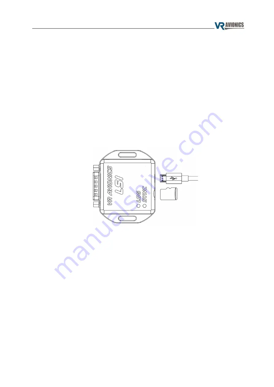
Besides an electrical connector, a slot for a micro SD card, and a slot for a USB cable, the LSI comes
equipped with LOG and SYNC lights to provide helpful feedback.
Logging Data
To log operational data you need a FAT32 formatted micro SD card with enough free space, and the
following folder structure:
●
Root folder named “LSI”,
●
Folder named “LOG” within the “LSI” folder
Note that should you wish to temporarily disable logging at any point while leaving the card in the LSI,
you may simply rename the LOG folder to something different, such as “#LOG”, and when you want to
resume logging again rename it back to “LOG”.
Only when a FAT32 formatted micro SD card with the prescribed folder structure is present in a powered
LSI, will logging be performed. The LOG light will indicate whenever logging is in progress.
The LSI will create a new log file inside the LOG folder at power-up and continue to log all operational
data of any connected VR LRU to that file until power down. Each log file is named LOG#####.VRL
where ##### constitutes a number from 0 to 99999. This number corresponds to a LSI configuration
setting called
Log File Incremental Reference Number
. Each new power up this number is automatically
incremented. You may override this configuration setting or any other as explained
To view any log file, open SetView and select File → Open Log File... from the top menu. Then browse to
the log file you want to view and select Open.
09/28/21
© 2021 VR Avionics
page 4 of 11


