XR3D-6 Maintenance & Troubleshooting
EM-XR3D-6-001-EN.D
5-17
©2011 VOTI Inc.
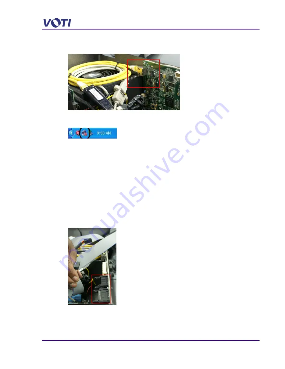
c) Look for flashing lights indicating communication at the RJ45 connector between the
detectors and the computer.
d)
Check the Network symbol on the monitor’s system tray also displays the Computer to
Control Unit connectivity.
e) If the cables are secure, reboot and restart the computer to see if this clears the
problem.
5.6.3 Partial Scanned Image
If when doing a scan only part of the image appears, check the ribbon cable connections.
If only the top of the image appears, check the ribbon cable connections of the TOP
detectors.
If only the bottom of the image appears, check the ribbon cable connections of the SIDE
detectors.
1. Open the Top Left Access Panel.
2. Remove the 2 screws securing the Computer cover and remove the cover.
3. Check the ribbon cable connections.
4. Perform a new scan to confirm if resetting the ribbon cables fixed the image display.
If all connections are correct, and image still not correct, replace the faulty detector group.
Summary of Contents for XR3D-6
Page 2: ...XR3D 6 Maintenance Troubleshooting ii EM XR3D 6 001 EN D 2011 VOTI Inc...
Page 6: ......
Page 20: ...XR3D 6 Maintenance Troubleshooting 2 8 EM XR3D 6 001 EN D 2011 VOTI Inc...
Page 32: ...XR3D 6 Maintenance Troubleshooting 3 12 EM XR3D 6 001 EN D 2011 VOTI Inc...
Page 48: ...XR3D 6 Maintenance Troubleshooting 3 28 EM XR3D 6 001 EN D 2011 VOTI Inc...
Page 52: ...XR3D 6 Maintenance Troubleshooting 4 4 EM XR3D 6 001 EN D 2011 VOTI Inc...


