background image

Drive Type

: The setting should be changed by authorized 

Volvo Penta personnel only.

ACP Mode

: Sets the ACP protection mode.

Toe Angle

: The setting should be changed by authorized 

Volvo Penta personnel only.

Speed Factor

: Calibrates the displayed boat speed.

PTA Settings

: Allows you to enter new maximum limits 

for the PTA modes.

Fuel Tank

: Sets the fuel tank settings.

Seven Marine Installation

: Sets the Seven Marine 

engine settings.

Hull ID Number

: Allows you to enter the Hull Identification 

Number (HIN).The HIN might be permanently affixed 
to the upper starboard side of the transom or outboard 
side.

Ignition Auto Off

: Turns off the ignition automatically after 

the engines have been off for the selected length of 
time.

Optimus Steering

: Allows you to adjust the Optimus 

steering parameters.

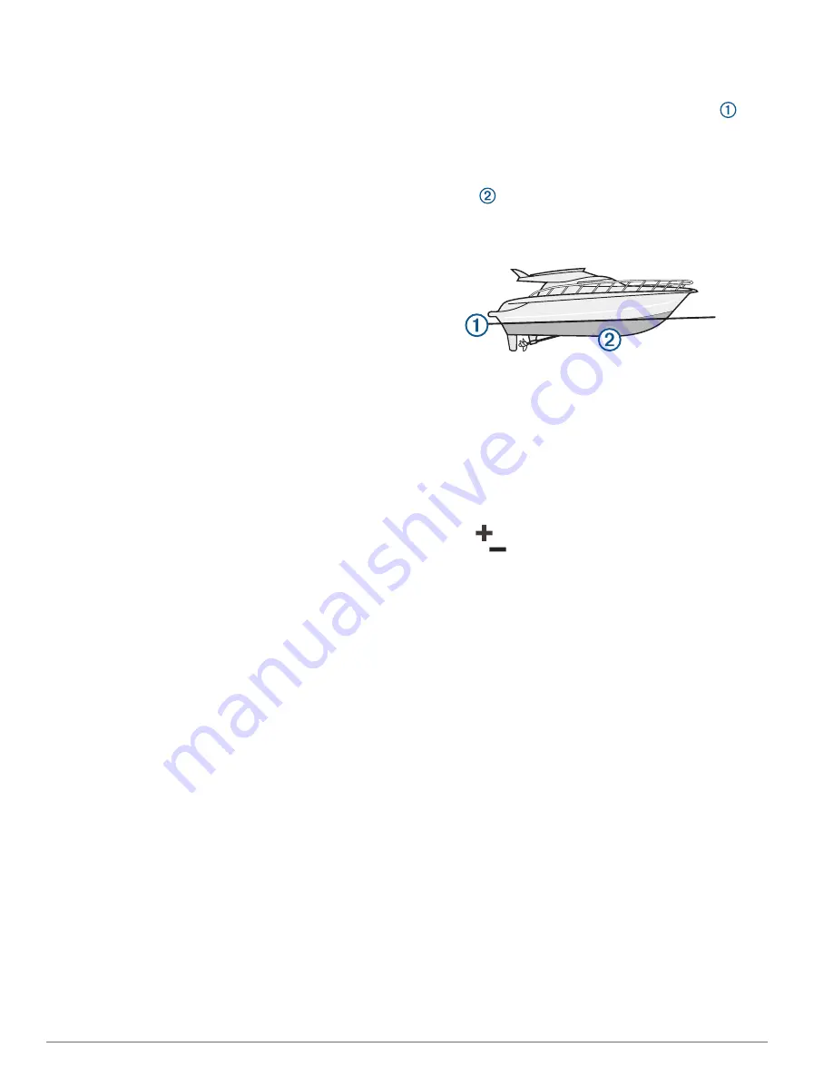
Setting the Keel Offset

You can enter a keel offset to compensate the water 
depth reading for the transducer installation location. This 
allows you to view the depth of the water below the keel or 
the true depth of the water, depending on your needs.
If you want to know the water depth below the keel or the 
lowest point of your boat and the transducer is installed 
at the water line or anywhere above the end of the keel, 
measure the distance from the transducer location to the 
keel of the boat.
If you want to know the true water depth and the 
transducer is installed below the water line, measure the 
distance from the bottom of the transducer up to the water 
line.

NOTE: 

This option is only available when you have valid 

depth data.

1

Measure the distance:
• If the transducer is installed at the water line 

 or 

anywhere above the end of the keel, measure the 
distance from the transducer location to the keel of 
the boat. Enter this value as a positive number.

• If the transducer is installed at the bottom of the 

keel 

 and you want to know the true depth of 

the water, measure the distance from the transducer 
to the water line. Enter this value in as a negative 
number.

2

Complete an action:
• If the transducer is connected to the chartplotter or 

a sonar module, select 

Options

 > 

Settings

 > 

My 

Vessel

 > 

Depth and Anchoring

 > 

Keel Offset

.

• If the transducer is connected to the NMEA 

2000 network, select 

Options

 > 

Settings

 > 

Communications

 > 

NMEA 2000 Setup

 > 

Device 

List

, select the transducer, and select 

Review

 > 

Keel Offset

.

3

Select 

 if the transducer is installed at the water line, 

or select 

 if the transducer is installed at the bottom 

of the keel.

4

Enter the distance measured in step 1.

Setting the Water Temperature Offset

The temperature offset compensates for the temperature 
reading from a temperature sensor or temperature-
capable transducer.

1

Measure the water temperature using the temperature 
sensor or temperature-capable transducer that is 
connected to the network.

2

Measure the water temperature using a different 
temperature sensor or a thermometer that is known to 
be accurate.

3

Subtract the water temperature measured in step 1 
from the water temperature measured in step 2.
This value is the temperature offset. Enter this value 
in step 5 as a positive number if the sensor measures 
the water temperature as being colder than it actually 
is. Enter this value in step 5 as a negative number if 
the sensor measures the water temperature as being 
warmer than it actually is.

86

Device Configuration

Summary of Contents for 8400

Page 1: ...Owners manual VOLVO PENTA GLASS COCKPIT ...

Page 2: ...t are trademarks of Garmin Ltd or its subsidiaries These trademarks may not be used without the express permission of Garmin Volvo Penta is a registered trademark of Volvo Trademark Holding AB Apple and Mac are trademarks of Apple Inc registered in the U S and other countries Android is a trademark of Google Inc The BLUETOOTH word mark and logos are owned by the Bluetooth SIG Inc and any use of su...

Page 3: ...ontrol 7 Enabling Voice Control 8 Supported Headsets 8 Pairing a Wireless Headset with a Garmin Chartplotter 8 Using a Wireless Headset with a Garmin Chartplotter 8 Chartplotter Voice Commands 8 GRID Remote Control 9 Pairing the GRID Device with the Chartplotter from the Chartplotter 9 Pairing the GRID Device with the Chartplotter from the GRID Device 9 Rotating the GRID Remote Input Device 9 Acti...

Page 4: ...re 23 Adding a Label to a Garmin Quickdraw Contours Map 23 Garmin Quickdraw Community 23 Connecting to the Garmin Quickdraw Community with ActiveCaptain 24 Connecting to the Garmin Quickdraw Community with Garmin Connect 24 Garmin Quickdraw Contours Settings 25 Navigation with a Chartplotter 25 Basic Navigation Questions 26 Route Color Coding 26 Destinations 26 Searching for a Destination by Name ...

Page 5: ... the Distance between the Bow and the GPS Antenna 34 Laylines Settings 34 Polar Tables 34 Importing a Polar Table Manually 35 Showing Polar Data in Data Fields 35 Setting the Keel Offset 35 Heading Line and Angle Markers 35 Setting the Heading Line and Angle Markers 36 Water Sport Controls 36 Creating a Water Sports User Preset 36 Renaming a User Preset Button 36 Setting the Boat RPM or Speed 36 S...

Page 6: ...ing and Adjusting a Radar No Transmit Zone 51 Adjusting the Radar Range 51 Tips for Selecting a Radar Range 51 MotionScope Doppler Radar Technology 51 Enabling a Guard Zone 52 Defining a Circular Guard Zone 52 Defining a Partial Guard Zone 52 MARPA 52 MARPA Targeting Symbols 52 Acquiring MARPA Targets Automatically 52 Removing MARPA Targets Automatically 52 Assigning a MARPA Tag to an Object 53 Re...

Page 7: ...ng 61 Networked Chartplotter and VHF Radio Functionality 61 Turning On DSC 62 DSC List 62 Viewing the DSC List 62 Adding a DSC Contact 62 Incoming Distress Calls 62 Navigating to a Vessel in Distress 62 Man Overboard Distress Calls Initiated from a VHF Radio 62 Man Overboard and SOS Distress Calls Initiated from the Chartplotter 62 Position Tracking 62 Viewing a Position Report 62 Navigating to a ...

Page 8: ... 69 Playing Music 70 Browsing for Music 70 Setting a Song to Repeat 70 Setting All Songs to Repeat 70 Setting Songs to Shuffle 70 Joining the Fusion PartyBus Network 70 Adjusting the Volume 70 Muting the Media Volume 70 Enabling and Disabling Zones 70 VHF Radio 70 Scanning VHF Channels 70 Adjusting the VHF Squelch 70 Radio 70 Setting the Tuner Region 70 Changing the Radio Station 70 Changing the T...

Page 9: ...anging a Camera 80 Viewing a Camera Feed Full Screen 80 Changing the Surround View Camera Layout 80 Showing and Hiding the Visual Bumper 81 Adjusting the Visual Bumper 81 Showing the Distance Marker 81 Renaming a Camera 81 Device Configuration 81 System Settings 81 Sounds and Display Settings 81 GPS Settings 81 Station Settings 82 Viewing System Software Information 82 Viewing E label Regulatory a...

Page 10: ... Software Updates 91 Cleaning the Screen 92 Viewing Images on a Memory card 92 Screenshots 92 Capturing Screenshots 92 Copying Screenshots to a Computer 92 Troubleshooting 92 My device will not acquire GPS signals 92 My device will not turn on or keeps turning off 92 My device is not creating waypoints in the correct location 93 Contacting Volvo Penta Support 93 Specifications 93 Glass Cockpit B7 ...

Page 11: ... ask that you read through the instruction manual carefully and take note of our advice on boat operations and maintenance before you make your first trip Pay attention to the safety instructions in the manual We would also like to welcome you to our world wide network of distributors and repair shops which can help you with technical advice service and spare parts The Volvo Penta website at suppo...

Page 12: ...are not guaranteed to be fully compatible in a combination page or SmartMode layout or when accessories such as a radar are connected Button Function Clears the on screen icons and re centers the screen on the boat Opens a full screen view of the item Creates a new waypoint Creates a route with turns to the destination Adds a turn to the route at the selected location Removes the last added turn f...

Page 13: ...using device features and accessing regulatory information 1 Go to garmin com manuals VolvoGlassCockpitB7 B9 B12 2 Download the manual Garmin Support Center Go to support garmin com for help and information such as product manuals frequently asked questions videos software updates and customer support Inserting Memory Cards This device supports up to a 32 GB microSD memory card formatted to FAT32 ...

Page 14: ...nges appear on only that display When you change the name and symbol of the layout those changes appear on all displays in the station to maintain a consistent appearance Pinning a Feature Button You can add features such as a chart combo screen or gauge to the Pinned category NOTE If your chartplotter has been customized by the boat manufacturer the Pinned category contains customized items for y...

Page 15: ...artplotter is turning on For the best fit the image should be 50 MB or less and conform to the recommended dimensions Recommended Startup Image Dimensions page 5 1 Insert a memory card that contains the image you want to use 2 Select Options Settings System Sounds and Display Startup Image Select Image 3 Select the memory card slot 4 Select the image 5 Select Set as Startup Image The new image is ...

Page 16: ...e interacting with the change appears only on that display except for the SmartMode name and symbol When you change the SmartMode name or symbol for the layout the new name or symbol appears on all displays in the station 1 Open a page to customize 2 Select Options 3 Select Edit Layout or Edit Combo 4 Select an option To change the name select Name or Name Symbol Name enter a new name and select D...

Page 17: ... A preset is a collection of settings that optimize the screen or view You can use particular presets to optimize groups of settings for your activity For example some settings might be optimal for when you are fishing and others might be optimal for when you are cruising Presets are available on some screens such as charts sonar views and radar views To select a preset for a compatible screen sel...

Page 18: ...provides a voice response Chartplotter Voice Commands The voice command system is designed to detect natural speech This is a list of commonly used voice commands but the device does not require these exact phrases other than OK Garmin You can try saying variations of these commands in a way that is natural to you An expanded list of voice commands is available at garmin com support marine_voice_c...

Page 19: ...e to the GRID 20 device 1 Select Options Settings Communications Marine Network 2 Select the GRID device ActiveCaptain App WARNING This feature allows users to submit information Garmin makes no representations about the accuracy completeness or timeliness of information submitted by users Any use or reliance on the information submitted by users is at your own risk The ActiveCaptain app provides ...

Page 20: ...app 1 From the GLASS COCKPIT device select ActiveCaptain Smart Notifications Enable Notifications 2 Turn on Bluetooth technology in the mobile device settings 3 Bring the devices within 10 m 33 ft of each other 4 From the ActiveCaptain app on the mobile device select Smart Notifications Pair with Chartplotter 5 Follow the on screen instructions to pair the app to the GLASS COCKPIT device 6 When pr...

Page 21: ...on your mobile device select Software Updates Download The ActiveCaptain app downloads the update to the mobile device When you reconnect the app to the GLASS COCKPIT device the update is transferred to the device After the transfer is complete you are prompted to install the update 3 When you are prompted by the GLASS COCKPIT device select an option to install the update To update the software im...

Page 22: ...r are updating a built in chart you need to follow the steps below once Then the content is downloaded automatically each day you open the ActiveCaptain app 1 When a chart update is available and you have internet access on your mobile device open the ActiveCaptain app on your mobile device 2 Select Chart My Charts 3 Select the map to update 4 Select the area to download 5 Select Download The Acti...

Page 23: ...ations Wireless Devices Wireless Remotes GPSMAP Remote Backlight 2 Follow the on screen instructions Disconnecting the Remote Control from All Chartplotters 1 On the chartplotter select Options Settings Communications Wireless Devices Wireless Remotes GPSMAP Remote Disconnect All 2 Follow the on screen instructions Wireless Wind Sensor Connecting a Wireless Sensor to the Chartplotter You can view ...

Page 24: ...or depth recognition This chart is best for offshore deep sea fishing NOTE The Fishing chart is available with premium charts in some areas Perspective 3D Provides a view from above and behind the boat according to your course and provides a visual navigation aid This view is helpful when navigating tricky shoals reefs bridges or channels and is beneficial when trying to identify entry and exit ro...

Page 25: ...uidance or to identify proper channels and are not intended to be precisely followed Always defer to the navaids and conditions on the water when navigating to avoid groundings or hazards that could result in vessel damage personal injury or death The Auto Guidance feature is based on electronic chart information That data does not ensure obstacle and bottom clearance Carefully compare the course ...

Page 26: ...ation purposes only It is your responsibility to heed all posted water related guidance to remain aware of your surroundings and to use safe judgment in on and around the water at all times Failure to heed this warning could result in property damage serious personal injury or death The icon on the chart indicates a tide station You can view a detailed graph for a tide station to help predict the ...

Page 27: ...w a perspective photo select The photo was taken from the location of the camera pointed in the direction of the cone 2 Select Photo Automatic Identification System The Automatic Identification System AIS enables you to identify and track other vessels and alerts you to area traffic When connected to an external AIS device the chartplotter can show some AIS information about other vessels that are...

Page 28: ...by an activated AIS target but rate of turn information is not provided the projected course of the target is calculated based on the course over ground information Activating a Target for an AIS Vessel 1 From a chart or a 3D chart view select an AIS vessel 2 Select AIS Vessel Activate Target Viewing Information about a Targeted AIS Vessel You can view the AIS signal status MMSI GPS speed GPS head...

Page 29: ...tplotter is connected to a compatible AIS radio To show AIS ATONs from a chart select Options Layers Chart Navaid ATONs You can view more information about an ATON if you select the ATON on the chart Symbol Meaning Real or synthetic ATON Real or synthetic ATON Topmark North Real or synthetic ATON Topmark South Real or synthetic ATON Topmark East Real or synthetic ATON Topmark West Real or syntheti...

Page 30: ...h setting is specific to the chart or chart view being used NOTE Not all settings apply to all charts and chartplotter models Some options require premium maps or connected accessories NOTE The menus may contain some settings that are not supported by your installed charts or your present location If you make changes to those settings the changes will not impact the chart view From a chart select ...

Page 31: ... you to set a layline based on the windward sailing angle Leeward Ang Allows you to set a layline based on the leeward sailing angle Tide Correction Corrects the laylines based on the tide Layline Filter Filters the layline data based on the time interval entered For a smoother layline that filters out some of the changes in the boat s heading or true wind angle enter a higher number For laylines ...

Page 32: ...ription Shows weather subscription information Restore Defaults Resets the weather settings to factory default values Edit Overlays Adjusts the data shown on the screen Customizing the Data Overlays page 6 Radar Overlay Settings From the Navigation or Fishing chart select Options Layers Radar From a radar screen select Options Radar To Standby Stops radar transmission Gain Adjusts the gain Adjusti...

Page 33: ...and a speed between 16 and 32 km h 10 and 20 mph A red circle indicates poor depth or GPS position and a speed above 32 km h 20 mph You can view Garmin Quickdraw Contours in a combination screen or as a single view on the map The amount of saved data depends on the size of your memory card your sonar source and the speed of your boat as you record data You can record longer when you use a single b...

Page 34: ...munity with Garmin Connect 1 Go to connect garmin com 2 Select Getting Started Quickdraw Community Getting Started 3 If you do not have a Garmin Connect account create one 4 Sign in to your Garmin Connect account 5 Select Dashboards Marine to open the Garmin Quickdraw widget TIP Make sure you have a memory card in your computer to share Garmin Quickdraw Contours maps Sharing Your Garmin Quickdraw ...

Page 35: ...and conditions on the water when navigating to avoid groundings or hazards that could result in vessel damage personal injury or death The Auto Guidance feature is based on electronic chart information That data does not ensure obstacle and bottom clearance Carefully compare the course to all visual sightings and avoid any land shallow water or other obstacles that may be in your path When using G...

Page 36: ...te might change to indicate when you should take caution Magenta Default route course line Thin purple Dynamically corrected course indicating you are off course Orange Caution This segment of the route may be near the thresholds of the Auto Guidance depth and height settings For example the route segment is orange when the route crosses under a bridge or is in potentially shallow waters Garmin Na...

Page 37: ...ation as a Waypoint From any screen select Mark Creating a Waypoint at a Different Location 1 Select Waypoints New Waypoint 2 Select an option To create the waypoint by entering position coordinates select Enter Coordinates and enter the coordinates To create the waypoint using a chart select Use Chart select the location and select Select To create the waypoint using a range distance and bearing ...

Page 38: ...oute to the location including turns select Route To To use Auto Guidance select Auto Guidance 5 Review the course indicated by the magenta line NOTE When using Auto Guidance a gray segment within any part of the magenta line indicates that Auto Guidance cannot calculate part of the Auto Guidance line This is due to the settings for minimum safe water depth and minimum safe obstacle height 6 Follo...

Page 39: ...nd Navigating Parallel to a Saved Route Before you can browse a list of routes and navigate to one of them you must create and save at least one route Creating and Saving a Route page 28 1 Select Info User Data Routes NOTE Auto Guidance is available with premium charts in some areas 2 Select a route 3 Select Navigate To 4 Select Offset to navigate parallel to the route 5 Select Offset to enter the...

Page 40: ...ation and select Next 4 Select an option To view a hazard and adjust the path near a hazard select Hazard Review To adjust the path select Adjust Path and follow the on screen instructions To delete the path select Cancel Auto Guidance To save the path select Done Adjusting a Saved Auto Guidance Path 1 Select Info User Data Routes 2 Select a path and select Review Edit Adjust Path TIP When navigat...

Page 41: ...nces Navigation Auto Guidance Shoreline Distance Far If the turns in the line are too wide select Options Settings Preferences Navigation Auto Guidance Shoreline Distance Near 7 If you selected Near or Far in step 6 review the placement of the Auto Guidance line and determine whether the line safely avoids known obstacles and the turns enable efficient travel Auto Guidance maintains a wide clearan...

Page 42: ... currently being recorded is called the active track 1 Select Info User Data Tracks Follow Active Track 2 Select an option Select the time the active track began Select Entire Log 3 Review the course indicated by the colored line 4 Follow the colored line steering to avoid land shallow water and other obstacles Clearing the Active Track Select Info User Data Tracks Clear Active Track The track mem...

Page 43: ... Boundaries 2 Select a boundary 3 Select Review Alarm 4 Select an option To set an alarm for when your boat is a specified distance from the boundary select Warning Dist enter a distance and select Done To set an alarm for when you enter or exit an area boundary or a circle boundary select Area to show Entering or Exiting Disabling all Boundary Alarms Select Info User Data Boundaries Alarms Deleti...

Page 44: ...ail Racing combination screen select Stop Setting the Distance between the Bow and the GPS Antenna You can enter the distance between the bow of your boat and the location of your GPS antenna This helps ensure the bow of your boat crosses the starting line at the precise start time 1 From a navigation chart select Options Sailing Start Line GPS Bow Offset 2 Enter the distance 3 Select Done Layline...

Page 45: ...e select Δ Target True Wind Angle To show the difference between the apparent wind angle and target apparent wind angle and the true wind angle select Δ Target App Wind Angle TIP You can also use the polar table data when calculating laylines and starting line guidance Setting the Keel Offset You can enter a keel offset to compensate the water depth reading for the transducer installation location...

Page 46: ...ings NOTE When the chartplotter is connected to a compatible Volvo Penta engine that supports the water sports feature you cannot control the chartplotter with the ActiveCaptain app on a mobile device Creating a Water Sports User Preset You can save your current water sports settings as a user preset to quickly return the chartplotter to your desired settings From the water sports page hold a user...

Page 47: ...our compatible chartplotter can be used as a fishfinder Chartplotter models without an xsv or xs in their names require a Garmin sounder module and transducer to display sonar information For more information about which transducer is best for your needs go to garmin com transducers Different sonar views can help you view the fish in the area The sonar views available vary depending on the type of...

Page 48: ... SideVü transducer SideVü scanning sonar technology shows you a picture of what lies to the sides of the boat You can use this as a search tool to find structures and fish Left side of the boat Right side of the boat The transducer on your vessel Logs Old tires Trees Water between the vessel and the bottom Distance from the side of the boat SideVü Scanning Technology Instead of a more common conic...

Page 49: ... what is below the boat and can be used to see a bait ball and fish Panoptix down view history in a scrolling sonar view Boat Range Trails Drop shot rig Bottom LiveVü Forward Sonar View This sonar view shows a two dimensional view of what is in front of the boat and can be used to see a bait ball and fish Boat Range Fish Trails Bottom RealVü 3D Forward Sonar View This sonar view shows a three dime...

Page 50: ...y need to update the transducer software LiveScope Sonar View This sonar view shows a live view of what is in front of or below the boat and can be used to see fish and structures Depth information Suspended targets or fish Bottom of the body of water Perspective View This sonar view shows a live view of what is around and ahead of your boat and can be used to see shorelines fish and structures Th...

Page 51: ...rces 2 Enter the name Creating a Waypoint on the Sonar Screen 1 From a sonar view drag the screen or select 2 Select a location 3 Select 4 If necessary edit the waypoint information Pausing the Sonar Display From a sonar view select Viewing Sonar History You can scroll the sonar display to view historical sonar data NOTE Not all transducers save historical sonar data 1 From a sonar view drag the s...

Page 52: ...ks best after you have adjusted the level of detail shown on the screen using the gain or brightness settings If you want to highlight smaller fish targets or create a higher intensity display of a target you can increase the color gain or contrast setting This causes a loss in the differentiation of the high intensity returns at the bottom If you want to reduce the intensity of the return you can...

Page 53: ...nge You can adjust the range of the depth scale for traditional and Garmin ClearVü sonar views You can adjust the range of the width scale for the SideVü sonar view Allowing the device to adjust the range automatically keeps the bottom within the lower or outer third of the sonar screen and can be useful for tracking a bottom that has minimal or moderate terrain changes Manually adjusting the rang...

Page 54: ...value is too high the targets blend together If the value is too low the targets are small and more difficult to see You can use echo stretch and filter width together to obtain the preferable resolution and noise reduction With echo stretch and filter width set to low the display has the highest resolution but is the most susceptible to noise With echo stretch set to high and filter width set to ...

Page 55: ...et edges and may also reduce noise This option is available on the Traditional sonar view only Flip Left Right Switches the SideVü view orientation from left to right This option is available on the SideVü sonar view only Restore Sonar Defaults Restores the sonar settings to the factory default values Transducers Allows you to change the transducer view details about the transducers and save detai...

Page 56: ... select To adjust the viewing angle vertically select To adjust the viewing angle swipe the screen in any direction To zoom in spread two fingers apart To zoom out pinch two fingers together Adjusting the RealVü Sweep Speed You can update how quickly the transducer sweeps back and forth A faster sweep rate creates a less detailed image but the screen refreshes faster A slower sweep rate creates a ...

Page 57: ...t results you should set the bow offset when using the front collision alarm Setting the Bow Offset page 48 1 From the FrontVü sonar view select Options FrontVü Alarm 2 Select On 3 Enter the depth at which the alarm is triggered and select Done On the FrontVü screen a depth line shows the depth at which the alarm is set The line is green when you are in a safe depth The line turns yellow when you ...

Page 58: ...ternal compass such as the PS21 TR transducer Orientation Controls if the transducer is in down or forward installation mode The Auto setting uses the AHRS sensor to determine the orientation This applies to PS22 transducers Restore Sonar Defaults Restores the sonar settings to the factory default values Setting the Bow Offset For forward view Panoptix transducers you can enter a bow offset to com...

Page 59: ...Settings page 49 Noise Reject Reduces noise and interference and attempts to remove returns that are not actually targets in the water Ghost Reject Reduces the occurrence of ghost images which are duplicated or reflected images that are not actually targets in the water The Ghost Reject setting sends more transmit power forward in the water to see farther with less noise generated by the bottom Ad...

Page 60: ... narrow beam of microwave energy as it rotates to a 360 pattern When the transmitted energy contacts a target some of that energy is reflected back to the radar Radar Interpretation Reading and interpreting the radar display takes practice The more you use the radar the better you will become at relying on the radar display when you really need it Radar can be useful in many situations such as avo...

Page 61: ...ransmitted and received by the radar As the range increases the radar transmits longer pulses in order to reach distant targets Closer targets especially rain and waves also reflect the longer pulses which can add noise to the Radar screen Viewing information about longer range targets can also decrease the amount of space available on the Radar screen for viewing information about shorter range t...

Page 62: ...us of each tagged object acquiring lost tracking or dangerous and the chartplotter can sound a collision alarm if the object enters your safe zone Before you can use MARPA you must have a heading sensor connected and an active GPS signal The heading sensor must provide the NMEA 2000 parameter group number PGN 127250 or the NMEA 0183 HDM or HDG output sentence MARPA Targeting Symbols Acquiring a ta...

Page 63: ...he projected heading time for AIS activated vessels select Proj Heading and enter the time To show the tracks of AIS vessels select Trails and select the length of the track that appears VRM and EBL The variable range marker VRM and the electronic bearing line EBL measure the distance and bearing from your boat to a target object On the Radar screen the VRM appears as a circle that is centered on ...

Page 64: ...alls can cause a very bright image of the target to appear on the Radar screen This image can obscure smaller targets located near it NOTE Depending upon the radar in use the gain setting configured for use in one radar mode may or may not be applied to other radar modes or to the Radar overlay 1 From a Radar screen or the Radar overlay select Options Gain 2 Select Down to lower the gain until the...

Page 65: ...oats and buoys This option is only available on Fantom models Echo Trails Enables you to track the movement of vessels on the radar screen This option is not available on xHD open array or HD HD radome models VRM EBL Shows the variable range marker VRM circle and the electronic bearing line EBL to allow you to measure the distance and bearing from your boat to a target object VRM and EBL page 53 G...

Page 66: ...he radar overlay select Options Radar Setup Source Select Options Settings Communications Preferred Sources Radar 2 Select the radar source Autopilot WARNING You are responsible for the safe and prudent operation of your vessel The autopilot is a tool that enhances your capability to operate your boat It does not relieve you of the responsibility of safely operating your boat Avoid navigational ha...

Page 67: ... activity and heading performance The higher the percentage the more the course deviates before the autopilot corrects it TIP In choppy conditions at low speeds increasing the Power Saver percentage reduces rudder activity Enabling Shadow Drive From the autopilot screen select Options Autopilot Setup Shadow Drive Enabled Autopilot Overlay Bar NOTE Not all options are available on all autopilot mod...

Page 68: ...with the intent of running alongside the location where the Williamson turn pattern was initiated The Williamson turn pattern can be used in man overboard situations 1 From the autopilot screen select Options Pattern Steering Williamson Turn 2 Select Engage Port or Engage Starboard Following an Orbit Pattern You can use the orbit pattern to steer the boat in a continuous circle around the active w...

Page 69: ...he autopilot is a tool that enhances your capability to operate your boat It does not relieve you of the responsibility of safely operating your boat Avoid navigational hazards and never leave the helm unattended You can wirelessly connect a Reactor autopilot remote control to the chartplotter to control the compatible Reactor autopilot system For more information about using the remote see the Re...

Page 70: ...he host of the Wi Fi network Changing the Wi Fi Host page 13 4 On the chartplotter select Options Settings Communications Wireless Devices Garmin Trolling Motor 5 On the trolling motor display panel press three times to enter pairing mode on the trolling motor display panel is solid blue as it searches for a connection to the chartplotter and turns green when the connection is successful After the...

Page 71: ...Shortcut Keys Enables the shortcut keys on the trolling motor remote control to work with this particular chartplotter The keys work with only one chartplotter at a time Restore Defaults Resets the trolling motor settings to the factory default values Assigning a Shortcut to the Trolling Motor Remote Control Shortcut Keys You can quickly open commonly used screens by assigning a shortcut key on th...

Page 72: ...distress call 1 Select Info Other Vessels DSC List 2 Select a position report call 3 Select Review Navigate To 4 Select Go To or Route To Man Overboard Distress Calls Initiated from a VHF Radio When the chartplotter is connected to a compatible VHF radio with NMEA 2000 and you initiate a man overboard DSC distress call from the radio the chartplotter shows the man overboard screen and prompts you ...

Page 73: ...f a DSC channel is limited to those channels that are available in all frequency bands The default channel is 72 If you select a different channel the chartplotter uses that channel for subsequent calls until you call using another channel 1 Select Info Other Vessels DSC List 2 Select a vessel or a station to call 3 Select Review Call with Radio Channel 4 Select an available channel Making an Indi...

Page 74: ...t fuel sensors to inputs 1 2 3 or 4 1 Select Options Settings My Vessel Seven Marine Installation Tank Preset 2 Select a tank level sensor to configure 3 Select Name enter a name and select Done 4 Select Type and select the type of sensor 5 Select Style and select the style of sensor 6 Select Tank Capacity enter the capacity of the tank and select Done 7 Select Calibration and follow the on screen...

Page 75: ...itivity 2 Adjust the level of sensitivity Vessel Information When the chartplotter is connected to a compatible EVC 2 0 Volvo Penta engine you can view information about the engine From the menu bar select My Vessel Status Maintenance Assistant When the chartplotter is connected to a compatible Volvo Penta engine you can view the time to the next engine service in engine hours remaining and days r...

Page 76: ...elect Reply 4 Select a message 5 Select Send Digital Switching Your chartplotter can be used to monitor and control circuits when connected to a compatible digital switching system For example you can control the interior lights and navigation lights on the vessel You can also monitor live well circuits To access the digital switching controls select Vessel Switching For more information about pur...

Page 77: ...old switch 1 for 5 seconds Switch 1 starts flashing 3 Press and hold switch 2 for 5 seconds The switch stops flashing and a message confirms the newly selected wiring option 4 Repeat the previous two steps until the device is configured for the wiring option that applies to your installation type NOTE After selecting option C the next configuration option in the cycle deactivates the interlocks so...

Page 78: ...ning Manager Steering Limp Home Tide Current and Celestial Information Tide Station Information WARNING Tide and current information is for information purposes only It is your responsibility to heed all posted water related guidance to remain aware of your surroundings and to use safe judgment in on and around the water at all times Failure to heed this warning could result in property damage ser...

Page 79: ... 4 Select Review Sorting and Filtering Messages 1 Select Info Alert Manager Sort Filter 2 Select an option to sort or filter the message list Saving Messages to a Memory Card 1 Insert a memory card into the card slot 2 Select Info Alert Manager Save to Card Clearing All of the Messages Select Info Alert Manager Clear Alert Manager Media Player NOTE The media player feature is not compatible with a...

Page 80: ... source connected to the Fusion PartyBus stereo To leave the Fusion PartyBus network you can select Source Leave PartyBus Adjusting the Volume Muting the Media Volume 1 From the media screen select 2 If necessary select Select Enabling and Disabling Zones If you have wired your vessel s speakers into zones you can enable needed zones and disable unused zones 1 From the media screen select Options ...

Page 81: ...n select countries only you must set the tuner region to a location where DAB signals are broadcast 1 Select the DAB source 2 Select Scan to scan for available DAB stations When scanning is complete the first available station in the first ensemble found begins playing NOTE After the first scan is complete you can select Scan again to re scan for DAB stations When the re scan is complete the syste...

Page 82: ...to save as a preset 3 Select an option If the media device is a FUSION Link capable stereo select Browse Presets If the media device is a GXM antenna select Options Presets Add Current Channel Parental Controls The parental control feature allows you to limit access to any SiriusXM channels including those with mature content When the parental control feature is enabled you must enter a passcode t...

Page 83: ...on changes Weather Warnings and Weather Bulletins When a marine weather warning weather watch weather advisory weather bulletin or other weather statement is issued shading indicates the area to which the information applies The aqua lines on the chart indicate the boundaries of marine forecasts coastal forecasts and offshore forecasts Weather bulletins may consist of either weather watches or wea...

Page 84: ...from a high pressure center results in decreased pressure Winds flow clockwise around high pressure centers in the northern hemisphere City Forecasts City forecasts appear as weather symbols The forecast is viewed in 12 hour increments Symbol Weather Fair sunny hot clear Partly cloudy Cloudy Rain drizzle sleet showers Thunderstorms Windy Smoke dusty hazy Foggy Snow snow showers flurries blizzard b...

Page 85: ...e color range dynamically to view higher resolution sea surface temperature readings 1 Select Charts Sea Temperature Options Sea Temperature 2 Select an option To allow the chartplotter to adjust the temperature range automatically select Auto Configure The chartplotter automatically finds the lower and upper limits for the current screen and updates the temperature color scale To enter the lower ...

Page 86: ...tplotter damages the Garmin chartplotter and may damage the Ethernet device Before you can view and control video devices such as IP cameras encoders and thermal cameras using your chartplotter you must have a compatible video device connected to your chartplotter and you must have a marine network cable Power over Ethernet PoE isolation coupler Go to garmin com for a list of compatible devices or...

Page 87: ...ly moving the camera may damage the camera NOTE This feature is available only when a compatible camera is connected You may need to update the camera software to use this feature You can control the movements of the connected video cameras that support panning tilting and zooming Controlling Video Cameras Using On Screen Controls On screen controls allow you to control pan tilt zoom PTZ cameras R...

Page 88: ...sword The app and the camera connect to the chartplotter s Wi Fi network You can control the camera using the chartplotter Controlling the VIRB Action Camera with the Chartplotter Before you can control a VIRB action camera with the chartplotter you must connect the devices using a wireless connection You can connect up to five VIRB action cameras to the chartplotter After you connect the VIRB act...

Page 89: ...ich lens or lenses the camera uses while shooting video Mirror Allows you to flip or mirror the video Rotation Allows you to rotate the camera angle Adding the VIRB Action Camera Controls to Other Screens Before you can control a VIRB action camera with the chartplotter you must connect the devices using a wireless connection Connecting a Wireless Device to the Chartplotter page 12 You can add the...

Page 90: ...d view camera screen You can include the bird s eye view as part of a combo with another screen such as a chart Individual camera feeds By default two individual camera feeds are shown on the surround view screen You can customize this to show only one camera instead You can quickly change which cameras are shown in these feeds Selected camera indicator This indicator shows which camera is shown i...

Page 91: ...s the device to display day or night colors You can select the Auto option to allow the device to set day or night colors automatically based on the time of day Startup Image Sets the image that appears when you turn on the device Startup Layout Sets the layout that appears when you turn on the device Audio Settings You can adjust audible alarms alerts and warnings that are sounded over connected ...

Page 92: ...the source You can also synchronize these settings across all devices that enable the Sync Filters setting Keyboard Layout Arranges the keys on the on screen keyboard Screenshot Capture Allows the device to save images of the screen Menu Bar Display Shows or automatically hides the menu bar when it is not needed Units Settings Select Options Settings Preferences Units System Units Sets the unit fo...

Page 93: ...te To Auto Guidance 5 Review the placement of the Auto Guidance line and determine whether the line safely avoids known obstacles and the turns enable efficient travel 6 Select an option If the placement of the line is satisfactory select Options Navigation Options Stop Navigation and proceed to step 10 If the line is too close to known obstacles select Options Settings Preferences Navigation Auto...

Page 94: ...s for available connected devices Naming Devices and Sensors on the Network You can name devices and sensors connected to the Garmin Marine Network and the NMEA 2000 network 1 Select Options Settings Communications 2 Select Marine Network or NMEA 2000 Setup Device List 3 Select a device from the list on the left 4 Select Review Change Name 5 Enter the name and select Done Marine Network The Marine...

Page 95: ... alarms you must have a compatible chartplotter connected to a weather device such as a GXM device and have a valid weather subscription 1 Select Options Settings Alarms Weather 2 Turn on alarms for specific weather events Setting the Fuel Alarm CAUTION The Beeper setting must be turned on to make alarms audible Sounds and Display Settings page 81 Failure to set audible alarms could lead to injury...

Page 96: ...tance If the transducer is installed at the water line or anywhere above the end of the keel measure the distance from the transducer location to the keel of the boat Enter this value as a positive number If the transducer is installed at the bottom of the keel and you want to know the true depth of the water measure the distance from the transducer to the water line Enter this value in as a negat...

Page 97: ...st compare the displayed vessel speed with an external data source for speed such as GPS or another vessel Before you can set the speed factor the vessel must be under way 1 Select Options Settings My Vessel Speed Factor 2 Enter the difference between the displayed speed and the external data 3 Verify that the two speed sources are displaying the same value Fuel Tank Settings Select Options Settin...

Page 98: ...anguage Map Datum Heading Position Format System Units Calibrate Water Speed Radar Antenna Size Chart Settings Chart Borders Hazard Colors Heading Line Land POIs Light Sectors Navaid Size Navaid Type Photo Points Preferred Depth Shallow Shading Service Points Vessel Icon Cannot be synced between all models Restoring the Original Chartplotter Factory Settings NOTE This affects all devices on the ne...

Page 99: ...ile select the file from the list and select Save to Card Updating Built In Maps with a Memory Card and Garmin Express You can update the built in maps using the Garmin Express computer application and a memory card 1 Insert a memory card into the computer s card slot Inserting Memory Cards page 3 2 Open the Garmin Express application If you do not have the Garmin Express application installed on ...

Page 100: ... software Yes Yes Update your Garmin charts Yes Yes Download new Garmin charts Yes Yes Access the Garmin Quickdraw Contours Community to download and share contours with other users Yes No Function ActiveCap tain mobile app Garmin Express desktop app Monitor and track your boat with the OnDeck system Yes No Sync a mobile device with your Garmin chartplotter Yes No Access the ActiveCaptain Communit...

Page 101: ...tplotter 17 Remove the memory card NOTE If the memory card is removed before the device restarts fully the update is not complete Software Updates You may need to update the software when you install a new device or add an accessory You can use the ActiveCaptain mobile app to update the device software Updating Software with the ActiveCaptain App page 11 You can also use the Garmin Express desktop...

Page 102: ...pture a screenshot of any screen shown on your chartplotter as a png file You can transfer the screenshot to your computer You can also view the screenshot in the image viewer Viewing Images on a Memory card page 92 Capturing Screenshots 1 Insert a memory card into the card slot 2 Select Options Settings Preferences Screenshot Capture On 3 Go to a screen you want to capture 4 Hold or for at least ...

Page 103: ...eate the waypoint again Contacting Volvo Penta Support Go to support garmin com for help and information such as product manuals frequently asked questions videos and customer support In the USA call 913 397 8200 or 1 800 800 1020 In the UK call 0808 238 0000 In Europe call 44 0 870 850 1241 Specifications Glass Cockpit B7 Specifications Dimensions W H D 192 3 140 3 74 1 mm 7 9 16 5 1 2 2 15 16 in...

Page 104: ...16 41 2 in Clearance to next obstruction behind chart plotter 93 6 mm 311 16 in 1 The device withstands incidental exposure to water of up to 1 m for up to 30 min For more information go to www garmin com waterrating Display size W H 262 1 164 2 mm 10 15 16 6 7 16 in 30 7 cm 12 1 in diagonal Display resolution WXGA 1280 800 pixels Weight 3 0 kg 6 6 lb Compass safe distance 45 cm 17 72 in Max power...

Page 105: ...el 130060 Label 1 Dependent upon the transducer 2 Dependent upon the transducer rating and depth 3 Dependent upon the transducer water salinity bottom type and other water conditions Transmit PGN Description 126464 Transmit and receive PGN list group function 126984 Alert Response Receive PGN Description 065030 Generator average basic AC quantities GAAC 126983 Alert 126985 Alert text 126987 Alert ...

Page 106: ...Water temperature VHW Water speed and heading WPL Waypoint location DSC Digital selective calling information DSE Expanded digital selective calling HDG Heading deviation and variation HDM Heading magnetic MWD Wind direction and speed MDA Meteorological composite MWV Wind speed and angle VDM AIS VHF data link message You can purchase complete information about National Marine Electronics Associati...

Page 107: ...65263 109 Engine coolant temperature 65263 110 Engine coolant level 65263 111 Engine fuel rate 65266 183 Engine average fuel economy 65266 185 Engine intake manifold 1 pressure 65270 102 Battery potential power input 1 65271 168 Transmission oil temperature 65272 177 Transmission oil pressure 65272 127 Fuel level 65276 96 Engine oil filter differential pressure 65276 969 Appendix 97 ...

Page 108: ...AB Volvo Penta SE 405 08 Göteborg Sweden March 2022 Printed in Taiwan 190 02784 00_0E ...

Reviews: