2018-01-25
*WBV.PU.002.EN VX136QDM2*
WBV.PU.002.EN
VX136QDM2 V2.0
1/ 78
WBV.PU.002.EN VX136QDM2 V2.0
Operating Instructions
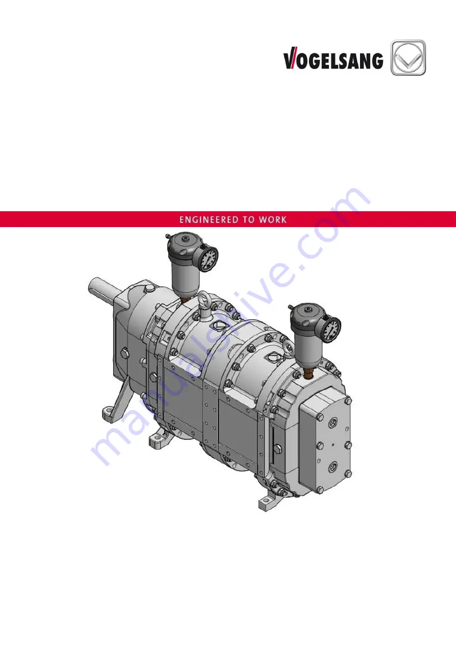
Rotary Lobe Pump
VX136QDM2
Page 1: ...2018 01 25 WBV PU 002 EN VX136QDM2 WBV PU 002 EN VX136QDM2 V2 0 1 78 2018 01 25 WBV PU 002 EN VX136QDM2 WBV PU 002 EN VX136QDM2 V2 0 Operating Instructions Rotary Lobe Pump VX136QDM2 ...
Page 2: ...ight to make technical modifications to the diagrams and information presented in this document in the event that such modifications become necessary for the enhancement of the machine 2018 Vogelsang GmbH Co KG Registered trademarks of Vogelsang In selected countries Vogelsang RotaCut HiFlo ACC CFC BioCrack XTill EnergyJet BioCut CC Serie PreMix ProTerra VarioCrop and XRipper are registered tradem...
Page 3: ...erial description for rotary lobes 12 3 2 Name plate 13 4 Safety 14 4 1 Operator s responsibilities 14 4 2 Personnel qualification 15 4 3 Fields of activity 15 4 4 Intended use 16 4 5 General safety notes 16 4 6 Warning and safety stickers on the machine 18 5 Transport storage 19 5 1 Transport 19 5 2 Storage 20 6 Assembly 21 6 1 Installation in pipe systems 21 6 2 Pipes 22 6 3 Direction of flow 23...
Page 4: ...ection and change 49 8 7 Greasing of sealing prechamber 51 8 8 Oils and lubricants 52 9 Repair 55 9 1 Conversion and spare parts 55 9 2 Opening the QD cover 56 9 3 Rotary lobe change 58 9 3 1 Lobe change for the 2nd stage B 58 9 3 2 Lobe change for the 1st stage A 59 9 4 How the lobe puller works 60 9 5 Change of wear plates 62 9 6 Change of cartridge mechanical seal 63 9 6 1 Change of cartridge m...
Page 5: ...nstallation example dry buffer chamber 47 Fig 19 Flushing operation 48 Fig 20 Gear oil change 50 Fig 21 Opening closing the QD cover 56 Fig 22 des Opening the QD cover with double hinge 57 Fig 23 Rotary lobe change 58 Fig 24 HiFlo and HiFloplus arrangement 59 Fig 25 Lobe puller components 60 Fig 26 Hooking puller arm into lobe 61 Fig 27 Pulling out the lobes with lobe puller 61 Fig 28 Installation...
Page 6: ...ir of the machine Vogelsang does not accept any liability for damage resulting from failure to comply with these operating instructions KEEP FOR FUTURE REFERENCE Please keep the manual ready at hand to ensure easy access to the necessary information at all times Additional copies of the manual are available upon request 1 2 Presentation convention Presentation Meaning Listing Sublisting 1 2 Carry ...
Page 7: ...this manual 1 If personal protective equipment is needed to work with and on the machine that is indicated by the following symbols Indicates that protective gloves must be worn for subsequent tasks Indicates that protective goggles must be worn for subsequent tasks Indicates that safety shoes must be worn for subsequent tasks ...
Page 8: ...y these symbols and words CAUTION Refers to a dangerous situation in which failure to comply with the safety note could result in light injuries WARNING Refers to a dangerous situation in which failure to comply with the safety note could result in death or serious injuries DANGER Refers to an extremely dangerous situation in which failure to comply with the safety note will result in death or ser...
Page 9: ... connectors Chapter Pump connector On a base or without a base Chapter Base support surface for machine With the following drive options Chapter Drive Electric drive Hydraulic drive PTO drive Combustion engine drive With or without system control Chapter System control The machines listed in these operating instructions are subject to the Machinery Directive 2006 42 EC see sample printout in Chapt...
Page 10: ...alth and safety requirements of the Machinery Directive 2006 42 EC in its design and construction and in the version marketed by us If a change is made to the machine without our agreement this declaration loses its validity Product Rotary lobe pump Applied harmonised standards DIN EN ISO 12100 2010 DIN EN 809 2012 The person or entity authorised to compile the technical documentation is Vogelsang...
Page 11: ...ve the material specific differential pressure limits Notice Theoretical operating torque with max differential pressure and water designed for NBR elastomers ATTENTION Speed reduction for highly viscous media When using the pump for a highly viscous medium the pump speed must be reduced according to the material s viscosity to prevent the intake flow from breaking off on the suction side cavitati...
Page 12: ...PU PU Werobust Polyurethane vulcanised 50 C Abrasive medium Wear resistant PUR PUR Polyurethane cast 80 C Abrasive medium Highly wear resistant CSM CSM Hypalon Chloro sulfonyl polyethylene rubber 80 C Petrol oil acids alkali solutions Wear resistant acid resistant and alkali resistant FPM FPM Fluorocarbon gum 80 C Solvents salt water oil petrol acids Acid resistant and alkali resistant Steel lobes...
Page 13: ... PU 002 EN VX136QDM2 V2 0 13 3 2 Name plate Fig 1 Name plate The name plate 1 contains the following details QR Code Product Design series Serial number Year of manufacture Weight Part number Address of Vogelsang GERMANY ...
Page 14: ...s used must be complied with The following applies in particular The operator shall ensure that all persons who handle the machine have read and understood this manual If necessary the operator shall train personnel and inform them of possible hazards To help keep track of training we recommend creating a training log The operator shall clearly regulate and define responsibilities for transport in...
Page 15: ... in serious injuries and property damage For this reason all activities must be performed by qualified personnel only Only persons who can be expected to perform their work reliably shall be permitted as personnel Persons whose ability to respond is impaired for example due to drugs alcohol or medication are not approved 4 3 Fields of activity The activities described in this manual may be perform...
Page 16: ...amage resulting from incorrect use Foreseeable misuse The machine is NOT intended for the following uses Potentially explosive atmospheres Operation subject to cavitation Use in the food industry without checking the specific hygiene requirements for the pump 4 5 General safety notes WARNING Risk of injury catching crushing collision due to rotating rotary lobes if the machine starts up unexpected...
Page 17: ...the connectors or the pipes can become very hot At high speeds or high differential pressure the gearbox housing can also become very hot Avoid accidental contact with hot surfaces Avoid dry running of the pump e g by means of dry running protection via Temperature monitor Level measurement Flow measurement ATTENTION Risk of frost To protect the pump against damage caused by frozen medium drain it...
Page 18: ...and must be replaced immediately if damaged or lost 1 VAU 133 2 VAU 138 3 VAU 115 4 VAU0050 Fig 2 Positions of the warning and safety labels example only the position of the stickers can vary depending on the size VAU 133 Before machine start up operating instructions must be read VAU 138 Buffer or quenching fluid tank VAU 115 Only used for pumps with a mechanical seal consisting of the material c...
Page 19: ... Cranes and hoists as well as forklifts must be designed for the weight of the transport units Standing under raised loads is prohibited Have people leave the danger area Permissible transport options for the machine suspended or bolted onto a Euro pallet In the case of suspended transport of the machine Remove the buffer fluid tank or quenching fluid tank before transport Use the lifting eye bolt...
Page 20: ...under 65 and the temperature should be between 5 C and 30 C The pump chamber can be sealed with a preservative that is compatible with the material of the lobes and gaskets The products should be protected against light especially direct sunlight and strong artificial light with a high ultraviolet component After a storage period of five years or more and before start up we recommend Checking and ...
Page 21: ...alling the pump ensure that there is easy access for maintenance work If the screw plugs for draining the gear oil and buffer or quenching fluid are not easy to reach discharge lines may be used part nos PBT 013 and or PBT 014 Ensure that the pump is installed tension free and that no tension can develop during operation either a b c d Fig 4 Installation variants a upright b horizontal c vertical ...
Page 22: ...igured for the weakest member WARNING Risk of injury from medium escaping under high pressure If the maximum pressure is exceeded Chapter Specifications parts may burst and the pumped medium may be expelled under high pressure Follow the recommendations for pipes Only use high pressure pipes on the discharge side Up to nominal diameter DN 150 PN 16 bar pipes Above nominal diameter 200 PN 10 bar pi...
Page 23: ...ameter of the suction pipe is too small the maximum suction height will be reduced by the loss of pressure due to pipe friction Contact us for a calculation Suction lines over 30 m must be laid with a slope of at least 2 x pipe diameter in the direction of flow ensuring that the pipeline can never run dry Fig Long suction lines Fig 5 Long suction lines 6 3 Direction of flow In the case of Marathon...
Page 24: ...tor drive If you are using motor driven pumps with one drive shaft the flow direction is selected by determining the direction of rotation of the drive motor such as an electric motor or hydraulic motor Preferred direction Fig 7 Flow direction with motor drive ...
Page 25: ...ith PTO drive If you are using tractor driven pumps with two drive shafts connect either the upper or lower cardan shafts thus determining the flow direction Cardan shaft in upper position Cardan shaft in lower position Fig 8 Flow direction with PTO drive ...
Page 26: ...eversal of the flow direction is not possible if the pipelines are protected by automatic check valves WARNING Risk of injury from medium escaping under high pressure If a connector has a sight glass the sight glass may burst if the pressure is too high A connector with a sight glass must be installed on the suction side The pressure may not exceed max 2 bar during reverse pumping A Sight glass Fi...
Page 27: ...ecified maximum permissible flange loads and bending moments for the pump connectors see Dimension sheet Tightening torques Hexagon head bolt M 10 10 9 steel 70 Nm Hexagon head bolt M 10 A4 70 stainless steel 40 Nm Retighten all bolts for fastening the connections after 20 operating hours and then every 2000 operating hours at least once a year ATTENTION Before installing stainless steel bolts and...
Page 28: ...pport surface Retighten all screws and nuts for fastening the motor and the machine to the base after 20 operating hours and then every 2000 operating hours at least once a year After fastening the machine to the base and the base to the ground on which the machine is standing the coupling orientation must be checked and realigned if necessary In addition also read and observe the following Coupli...
Page 29: ...pling must be complied with To protect the machine against damage caused by vibrations check the orientation of the coupling before start up and then every 2000 operating hours at least once a year and correct it as necessary Fig Orientation procedure If alignment errors are determined or after any blockage e g by foreign matter check the function of all parts of the drive line and readjust it if ...
Page 30: ...e repairs or troubleshooting once all the protective equipment has been re installed Check the fixed screw connection of the coupling guard after the first 20 operating hours and then every 2000 operating hours at least once a year Fig 12 Coupling guard Pos Quantity Part no Denomination Tightening torque 1 2 GZS0337 Coupling guard individual part 2 1 GZS0333 Separation mat 3 1 GZS0335 Safety plate...
Page 31: ...e exposed rotating drive shaft coupling The coupling area must be protected by a screwed cover The machine may only be started up again after maintenance repairs or trouble shooting once all the protective equipment has been re installed Before starting assembly and repair work on the coupling switch the machine off and secure it against being switched on again 6 6 1 Electric drive Connection to t...
Page 32: ...layout diagram on the inside of the motor terminal box cover Note that the PTC resistor of the geared motor must be connected to the terminals provided on the pump control to a PTC control unit or to a variable frequency drive with a PTC input each available as an option Install a maintenance switch in close proximity to the machine recommendation Before start up or long term storage The seal on t...
Page 33: ... pressure and the permissible delivery rate Connect the overflow oil line in accordance with the manufacturer s instructions Replace hydraulic hose lines that show signs of damage or ageing Only use genuine Vogelsang hydraulic hose lines The date of manufacture of the hydraulic hose line is displayed on the pressing component of the connector The period of usage for the hydraulic hose line should ...
Page 34: ...engine exhaust gases can lead to a loss of consciousness and death Never operate the engine in enclosed or poorly ventilated spaces Do not breathe in exhaust gases DANGER Fire hazard due to fuel Leaking or spilled fuel can ignite on hot motor parts and cause serious burns Only refuel when the engine is switched off Never refuel in the vicinity of open flames or ignitable sparks Do not smoke Do not...
Page 35: ...tion and make sure that the components to be installed are clean WARNING Risk of catching hands or work clothing in the rotating shaft end without cardan shaft There is a risk of injury due to accidental contact with the exposed rotating shaft end Before start up operation make sure that a suitable PTO shaft guard is installed If no suitable PTO shaft guard is present please request one from us Op...
Page 36: ...uires monitoring equipment Machines that are operated in automatic mode must be equipped with a temperature and pressure monitoring system This monitoring equipment can be obtained from us as an option Variable frequency drive operation In general rotary lobe pumps can be used in variable frequency drive operation Advantages Adaptation to operating conditions viscosity delivery rate NPSHavail Wear...
Page 37: ...g up the machine in the presence of persons who are responsible for further operation of the machine WARNING Risk of injury catching by rotating rotary lobes The pump may only start up if the inlet and outlet pipes are connected so that access to the rotating rotary lobes in the pumping chamber is not possible ...
Page 38: ...ld be suitable for heavy starting Is the motor connected correctly to the hydraulic lines if applicable documents provided by the motor manufacturer Buffer chamber pump gearbox Are the optional buffer chamber assemblies correctly installed Are they correctly adjusted Is the buffer chamber pressure OK if applicable Is the type of buffer or quenching fluid OK Is the fluid level in the buffer chamber...
Page 39: ...r chamber pressure To protect against fluids spraying out carefully and slowly open the buffer chamber the bearing cover on the QD cover and the gearbox Cover the valves or screws to be removed with a cloth or similar item where appropriate 8 1 Buffer chamber In the following chapters we describe the following possible buffer chamber assemblies 1 Chapter Pressurisable buffer fluid tank 2 Chapter D...
Page 40: ... chamber Fill the tank about one quarter full when delivered the buffer chamber is already filled 4 Close the tank and use a manual air pump or a compressed air supply outlet to set the required tank pressure Topping up buffer fluid maintenance and inspection Fig Buffer fluid tank and Filling draining the buffer chamber 1 Release the pressure in the buffer chamber via the valve on the tank 2 Open ...
Page 41: ...V PU 002 EN VX136QDM2 V2 0 41 Upright installation Horizontal installation Vertical installation Suspended installation Fig 15 Filling draining the buffer chamber 1 Screw plug A Filling 2 Buffer fluid tank B Draining ...
Page 42: ...l and should not exceed 10 bar with a double mechanical seal Rotary lobe change and Cartridge mechanical seal change Before a rotary lobe and Cartridge mechanical seal change reduce the tank pressure and increase it again after changing Trouble indication Possible indications of trouble in the sealing system after the running in period Severe contamination of the buffer fluid in the tank Buffer fl...
Page 43: ...quenching fluid tank and the topping up of quenching fluid is as described in Chapter Pressurisable buffer fluid tank The instructions for pressurising the tank do not apply in the case of buffer chamber assembly depressurised quenching fluid tank Please also observe the Trouble indication and Buffer fluid properties in Chapter Pressurisable buffer fluid tank 1 Screw plug installation tightening t...
Page 44: ...ffer fluid leave a buffer of air above it about 1 cm distance between the oil level and the bearing seal housing Fig Pump with pressure valve The air buffer prevents the buffer chamber fluid from escaping through the pressure valve due to thermal expansion 1 Pressure valve A Air buffer B Oil level Fig 17 Pump with pressure valve 8 2 4 Plugs The buffer chamber assembly with plugs is used only for s...
Page 45: ...ome in contact with the medium are made of stainless steel Guideline depending on the buffer chamber assembly Chapter Buffer chamber 8 2 7 Buffer or quenching fluid inspection and change Buffer fluid or quenching fluid Check After the first 20 operating hours Every 200 operating hours Electronic buffer chamber monitoring is possible Ask us replace Every 2000 operating hours When there is severe co...
Page 46: ...r fluid tank or pressure valve depressurise the buffer chamber before draining or cleaning 2 Remove the buffer chamber assemblies 3 Undo the lower screw plug 1 Fig Filling draining the buffer chamber or Fig Pump with quenching fluid tank and drain the buffer or quenching fluid from the buffer chamber 4 If there is severe contamination clean the buffer chamber 5 Screw the lower screw plug back in t...
Page 47: ...he plug from the vent screw 5 Fig Installation example dry buffer chamber and completely fill the pump chamber with fluid Combination of mechanical seal rings in this sealing system Type of construction block ring Mating materials AISI 304 AISI 316 Ti tungsten carbide coated carbon Installation Fig Installation example dry buffer chamber Connect tank 3 with connecting pipe 4 at the bottom of the b...
Page 48: ...ushing pressure and volume flow Fig Flushing operation connection example for flushing pressure and volume flow adjustment Adjusting the flushing pressure The flushing pressure can be adjusted and monitored with a pressure gauge The flushing pressure should be about 0 5 bar higher than the average pressure in the pump Flushing pressure 0 5 bar pressure on the suction side pressure on the discharge...
Page 49: ...idge mechanical seals Note with this alternative flushing operation A possible defect cannot be assigned to the single cartridge mechanical seal Possible impurities of the cartridge mechanical seal rinsed for the first time can get into the subsequent mechanical seal 8 6 Gearbox 8 6 1 Gear oil grade We recommend the oils listed in Chapter Oils and lubricants 8 6 2 Gear oil quantity 2 litres 8 6 3 ...
Page 50: ...ended installation Fig 20 Gear oil change 1 Screw plug A Filling 2 Magnetic screw plug B Draining 3 Grease nipple C Checking The screw plug 1 must be at the top the magnetic screw plug 2 must be at the bottom Tightening torque ut 39 mod_1259315210400_6 doc 141472 Tightening torque for mounting the screw plugs 60 Nm ...
Page 51: ...l ATTENTION A regular lubrication interval prevents the lubrication channel from clogging To ensure effective distribution of the lubricant always lubricate while the machine is running and not when it is stationary Lubricating grease type We recommend the lubricating grease listed in Chapter Oils and lubricants Lubricating grease quantity Grease nipples 4 x at gearbox side 5 shots per grease nipp...
Page 52: ... 260 C DIN ISO 2592 Pour point 42 C DIN ISO 3016 Damage loading step 12 Water hazard class Slightly hazardous to waters When using BSS0021 oil for the pump gearbox the maintenance interval for checking and changing the gear oil may be doubled Chapter Maintenance plan Part number BSS 010 Description Medical white oil water white non fluorescent tasteless and odourless mixture of hydrocarbons Trade ...
Page 53: ...nt 210 C DIN ISO 2592 Pour point 24 C DIN ISO 3016 Damage loading step 12 Water hazard class Slightly hazardous to waters Part number BSS 016 Description Biodegradable environmentally friendly multigrade hydraulic oil based on rape seed oil as per ISO 15308 type HETG Trade name Fuchs Hydraulic oil 40 N Characteristics Test acc to ISO VG 46 DIN 51519 Viscosity index 220 DIN ISO 2909 Kinematic visco...
Page 54: ...al gear oil based on selected polyglycols PAG Trade name Fuchs Renolin PG 46 Characteristics Test acc to ISO VG 46 DIN 51519 Viscosity index 203 DIN ISO 2909 Kinematic viscosity at 40 C 46 mm s DIN 51562 Flash point 240 C DIN ISO 2592 Damage loading step 12 Water hazard class Slightly hazardous to waters 5 Lubricant for pump grease nipples Part number BSS 002 Description Lithium soap grease with a...
Page 55: ...table protective clothing The operator must inform his or her staff about any potentially hazardous substances in working materials or media ATTENTION Before installing stainless steel bolts and stainless steel nuts Clean threads and contact surfaces Apply anti seize paste part no BKL 014 BAS 001 evenly and in sufficient quantity to the screw head face and bearing face and to the thread using a br...
Page 56: ... head bolts or threaded rods on the QD cover 4 6 Remove the screw plugs 1 carefully as medium could spurt out due to pressure in the pump housing Where appropriate cover the plugs to be removed with a cloth or similar item 7 Undo strain bolts 2 8 Using the hexagon head bolts M10 for VX136 M12 for VX186 215 230 the QD cover can be pressed off via the threads 6 until the QD cover is loose Attention ...
Page 57: ...Repair WBV PU 002 EN VX136QDM2 V2 0 57 Fig 22 des Opening the QD cover with double hinge 1 QD cover 2 Double hinge ...
Page 58: ...shafts in pairs Chap How the lobe puller works 3 To install the new lobes follow the same sequence in reverse Fig Arrangement of HiFlo and HiFloplus When assembling solid material lobes please note fit an O ring 8 6 on the gearbox side and cover side of each lobe The O rings shown in the figure 8 6 are not present with rubberised lobes not solid material lobes 4 Close QD cover Chap Closing the QD ...
Page 59: ...he lobe puller works 9 To install the new lobes follow the same sequence in reverse Fig Arrangement of HiFlo and HiFloplus When assembling solid material lobes please note fit an O ring 6 8 on the gearbox side and cover side of each lobe The O rings shown in the figure 6 8 are not present with rubberised lobes not solid material lobes 10 Continue assembling in reverse sequence Attention observe th...
Page 60: ...e mechanical seal change VX136 140 210 280 420QDM2 part no PBA B033 T2 1 Hexagon head bolt 2 Puller arm 3 Pressure rod 4 Stabilisation 5 Wing nut Fig 25 Lobe puller components 1 Undo the four hexagon head bolts 1 and the wing nut 5 so that the puller arms 2 can be moved 2 Hook the two puller arms 2 into the groove provided on the lobe Fig Hooking puller arm into lobe 3 Tighten the wing nut 5 and h...
Page 61: ...ng puller arm into lobe Fig 27 Pulling out the lobes with lobe puller Maintenance instructions for lobe puller Regularly check the puller arms for wear and breakage Keep the threaded bolt in the pressure rod clean at all times and lubricate it regularly ...
Page 62: ... rotary lobes the correct installation position of the wear plate must be observed during installation Fig Installation position of the curved wear plates Tightening torque Wear plate screws 40 Nm 1 Wear plate on the gearbox 2 Wear plate on the cover 3 Hexagon head screw with microencapsulation Fig 28 Installation position of the curved wear plates ...
Page 63: ...mechanical seal evenly using the three hexagon head bolts 3 of the tool A Fig b 9 Change O ring 4 in the bearing seal housing Fig c 10 Before installing the new cartridge mechanical seal carefully remove the burrs on the keyways and clean the cartridge mechanical seal seat in the pump housing 11 Push new cartridge mechanical seal onto the shaft Carefully oil the outer O rings on the seal carrier p...
Page 64: ...BV PU 002 EN VX136QDM2 V2 0 a b c Fig 29 Cartridge mechanical seal on the gearbox 1 Set screw 4 O ring bearing seal housing 2 Cylinder head bolt 5 O ring seal carrier 3 Hexagon head bolt A Tool included in WKZ0172 ...
Page 65: ... seal evenly using the three hexagon head bolts 9 of the tool A 10 Place washer 13 on hexagon head bolt 14 and push it through the bearing cover 11 Change O ring 12 in the bearing seal housing 12 Clean cartridge mechanical seal in the QD cover 13 Insert new cartridge mechanical seal 11 14 If a circulation system is present the flushing connector boreholes in the cartridge mechanical seal must be a...
Page 66: ...l carrier 6 O ring 7 Set screw 8 Cylinder head bolt 9 Hexagon head bolt 10 Hexagon nut 11 Cartridge mechanical seal 12 O ring 13 Washer 14 Hexagon head bolt A Tool WKZ0456 includes pos 8 9 B Tool WKZ0119 C Tool WKZ0171 included in tool with part no WKZ0172 Fig 30 Cartridge mechanical seal on the QD cover ...
Page 67: ...xagon head bolts or threaded rods Attention Do not tilt the QD cover while doing this but press it evenly by hand no tools Make sure the O ring is seated correctly Tightening torques Hexagon nut M 10 10 9 70 Nm Hexagon nut M 10 A4 70 40 Nm 6 Tighten the strain bolts Tightening torques Tighten the M16 strain bolt 10 9 steel with 200 Nm then loosen it and tighten again with 140 Nm Tighten the M16 st...
Page 68: ...Repair 68 WBV PU 002 EN VX136QDM2 V2 0 1 Clean thoroughly and oil 2 Clean thoroughly Fig 31 Cleaning before QD cover assembly ...
Page 69: ...ring pins of the upper and lower pump housing segments to both sides Fig Adjustment of pump housing segments 4 Before installation of the pump housing segments apply flange sealant set a flat gasket in place and coat that gasket with flange sealant as well 5 Screw all bolts back onto the pump and the connectors Chap Pump connector 6 Install the QD cover Chap Closing the QD cover Fig 32 Adjustment ...
Page 70: ...een the lobes and wear plates Please note increasing the gap between lobes and wear plates reduces the volumetric efficiency Gap increase 1 mm On gearbox side and cover side Replace the wear plates PFL B009 5 mm with PFL B009 T1 4 mm Gap increase 0 3 mm On gearbox side and cover side Replace the wear plates PFL B009 5 mm with PFL B009 T2 4 7 mm ...
Page 71: ... not priming Fill the pump with fluid B Incorrect direction of rotation Change the pump s direction of rotation Flow direction C Pipe causing pump housing warping Check the orientation of the pipe to the pump If necessary provide a compensator or secure the pipe Installation in pipes D Leakage in the suction pipe Check the suction side pipe system for leakage Gas formation Vent the suction pipe an...
Page 72: ...uffer chamber Maintenance R Differential pressure too high Reduce differential pressure Specifications S Medium viscosity above the nominal value Reduce speed Increase medium temperature Intended use T Medium viscosity below the nominal value Increase speed decrease medium temperature replace wear parts Repair Gaps too large Reduce gaps Chapter Reducing the starting torque but with the procedure r...
Page 73: ...en undoing screws and bolts 3 Drain working materials Drain the gear oil from the pump gearbox Observe notices and safety notes Chapter Gear oil inspection and change Drain the buffer or quenching fluid from the buffer chamber Observe notices and safety notes Chapter Draining and cleaning the buffer chamber 4 Drain the pump and remove residual medium Observe notices and safety notes when opening t...
Page 74: ...74 WBV PU 002 EN VX136QDM2 V2 0 Maintenance and service plan ...
Page 75: ...hanical seal with SiC SiC material combination that are not put into operation immediately needs to be turned at least one revolution about every two months 12 2 Maintenance intervals ATTENTION Carefully observe the following maintenance intervals and document them in the service plan Chap Service plan Before start up Check pump motor coupling orientation base C Before start up and before and afte...
Page 76: ...ews fastening the pump connectors Retighten the bolts and nuts securing the machine without base Retighten the screws and nuts for fastening the motor and the machine on the base Check fixed coupling of coupling guard base C Check pump motor coupling orientation base C Change the buffer or quenching fluid Change the gear oil ...
Page 77: ...____ Retighten the screws for the pump connectors Retighten the screws for the base or machine attachment Check that the coupling guard is screwed on tight base C Check pump motor coupling orientation base C Lubricate grease nipples Check the buffer or quenching fluid Check the buffer or quenching fluid Check gear oil Change gear oil Others maintenance instructions Operating hour meter Total capac...
Page 78: ...lowenien VGS TECH GREGOR TURSIC S P vogelsang info Dänemark Vogelsang A S vogelsang as dk Malaysia Vogelsang Malaysia vogelsang info Schweden Vogelsang Sverige AB vogelsang se Deutschland Niederlassung Ost Vogelsang Lutherstadt Eisleben vogelsang info Mexico Vogelsang De México S de R L de CV vogelsang mx Spanien Vogelsang S L vogelsang es Finnland Vogelsang Oy vogelsang fi Niederlande Bos Benelux...