background image

2016/8/26


CaMate


Series


User’s


Manual


Rev0.1


Introduction

The 


CaMate


illuminators' 


variable 


beam 


angles 


can 


be 


adjusted 


via 


an 


RS485 


connection. 


Using 


a


USB‐to‐RS485


  converter,


  the


  LED


  ON/OFF,


  trigger


level,


Dimming,


Fade 


in/out 


can 


be 


remotely 

controlled. 


Configuration


&


Control


CaMate


can


be


configured


and


controlled


through


the


RS485


interface


and/or


a


remote


controller.


A


PC


or


Android


mobile


phone


can


be


used


to


configure


CaMate


through


the


RS485


interface.


You


can


download


a


Windows


application


software


and


Andriod


APP


from


"

www.vivotek.com\CaMate\app

."


Devices


that


come


with


the


RS485


interface,


e.g.


camera,


can


configure


and


control


CaMate


through


the


RS485


interface


with


a


correct


command


set


(refer


to


Appendix


A).


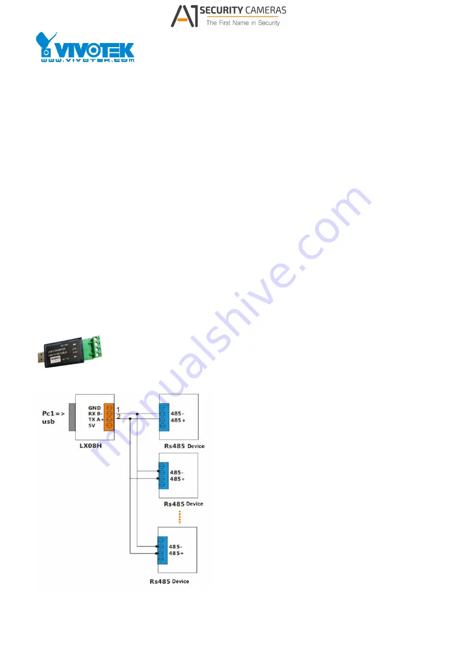
To


connect


a


PC


or


Android


device


to


a


CaMate


illuminator


via


the


RS485


interface,


an


USB

to

RS485


converter


should


be


used.


The


converter


is


separately


purchased.


An


example


is


shown


below:


An


exemplary


connection


should


look


like


this:


1


                    Available from A1 Security Cameras 

     www.a1securitycameras.com   email: [email protected]

Summary of Contents for CaMate Series

Page 1: ...CaMate through the RS485 interface You can download a Windows application software and Andriod APP from www vivotek com CaMate app Devices that come with the RS485 interface e g camera can configure and control CaMate through the RS485 interface with a correct command set refer to Appendix A To connect a PC or Android device to a CaMate illuminator via the RS485 interface an USB to RS485 converter...

Page 2: ...or value of 120Ω or greater should be used and no more than 2 termination resistors should be used one at each end of the RS485 transmission line Available from A1 Security Cameras www a1securitycameras com email sales a1securitycameras com 2 ...

Page 3: ...drate of CaMate default is 38 400 you can use the Baudrate probe icon to search for the correct baudrate 2 Then configure the correct baudrate and click the Find icon A search device window will prompt to ask for a start Device ID number Default is 1 Unless a change to the device ID of your CaMate was made otherwise press OK to start finding from device ID 1 You can press the Stop scan button any ...

Page 4: ...Available from A1 Security Cameras www a1securitycameras com email sales a1securitycameras com 4 ...

Page 5: ...l be listed under the selected COM port Select the CaMate you want to configure and or control and the Configuration Status page will display Available from A1 Security Cameras www a1securitycameras com email sales a1securitycameras com 5 ...

Page 6: ...n before you start to configure Device Info Device Info indicates the CaMate model name e g CM48I8 1040 LED Status LED Status depicts the current ON OFF state of LED Red means OFF and Green means ON Device ID Each device comes with a unique Device ID when multiple CaMate devices are present on the RS485 bus The Device ID ranges from 0 to 127 Make sure you configure different IDs for CaMate devices...

Page 7: ...orized CM48I8A 1040 31 CM48I8A 2040 32 CM48I8A 4080 33 CM48I8A 90120 34 IR 940 motorized CM48I9A 1040 41 CM48I9A 2040 42 CM48I9A 4080 43 CM48I9A 90120 44 W5 motorized CM48W5A 1040 51 CM48W5A 2040 52 CM48W5A 4080 53 CM48W5A 90120 54 Baudrate Baudrate sets the communication speed of CaMate devices on the RS485 interface The Max rate is 115 200 and the min is 1 200 The default baudrate is 38 400 Reme...

Page 8: ... associated configuration is DI DO active polarity which defines the activation polarity of DI e g low voltage or high voltage The DI DO status shows the current state of DI and DO signal The DI mode applies when the application prefers a control signal from an external device e g a network camera or a PIR detector Available from A1 Security Cameras www a1securitycameras com email sales a1security...

Page 9: ...t mode In the Direct control mode the IR LED is controlled by the commands issued through the RS485 interface Available from A1 Security Cameras www a1securitycameras com email sales a1securitycameras com 9 ...

Page 10: ...status If the Ambient Light is lower than the Trigger Level LED turns ON If higher than the Trigger level the LED turns OFF Fade in out The Fade in out control defines the LED ON OFF behavior If the Fade in out function is disabled the LED is turned ON or OFF immediately When the Fade in out is set to FAST the LED fades in or out in 1 second and 3 seconds if set to SLOW Fade in out can avoid sudde...

Page 11: ...ite value which means the light sensor detection is always active When the ambient light falls under the triggering threshold the LEDs enter the active state and will become inactive state when the light level is 10 above the threshold e g when the detected level is 30 Available from A1 Security Cameras www a1securitycameras com email sales a1securitycameras com 11 ...

Page 12: ...flashes means the device received and executing commands If both red and green LEDs flash simultaneously the device upgrading its firmware Ambient Light Ambient Light reports the current ambient lighting level The ambient light level is polled every 10 seconds The light sensor detection control may have a max of 10 seconds delay when the ambient light level changes LED Light Level LED Light Level ...

Page 13: ...mode In the LED state mode the DO pin outputs the LED ON OFF state If a CaMate is operating in the Direct or Light sensor LED control mode other devices can acknowledge the CaMate s LED ON OFF status via the DO connection DO Diagnostic mode In the Diagnostic mode the DO pin outputs the LED health status Abnormal conditions may include LEDs overheated or LED voltage out of range The Diagnostic mode...

Page 14: ... operation and the current voltage reading The Out of range count records the event when the input voltage is under DC12V 10 DC10 8V or over the AC24V 10 AC26 4V LED Voltage The LED voltage reports the health condition for LED strings as there are 4 LED strings in CaMate The normal LED ON voltage should fall between 400mV and 1200mV The Over range count records the event when the detected LED volt...

Page 15: ...e reliability and longevity MCU Temperature MCU temperature records the Max temperature ever happened to MCU current temperature reading and the count of overheating events Boot count How many times the device is power on and off It can be used to check if power losses have occurred in the operation history Error code The Error code is used for diagnostics purposes You can report the error code to...

Page 16: ... Select Firmware Upgrade the Firmware Upgrade window will prompt 1 Select the correct COM port Baudrate and Device ID then click the OPEN COM button When a CaMate is connected current firmware version and checksum will be read and shown Available from A1 Security Cameras www a1securitycameras com email sales a1securitycameras com 16 ...

Page 17: ... and select the correct binary file The new firmware version and checksum will display after loading You can find the firmware binary file at www vivotek com or contact your sales representative 3 Click FW Update and confirm the upload firmware upgrade will then start Please do not turn off the power to CaMate untill the upgrade is completed Available from A1 Security Cameras www a1securitycameras...

Page 18: ...Available from A1 Security Cameras www a1securitycameras com email sales a1securitycameras com 18 ...

Page 19: ...v Chks Firmware revision and checksum of the code Max Current Allowed max LED current It depends on hardware circuitry design Default Current Default LED current configuration Lens angle Optical Lens used in CaMate e g 10 40 Factory Date Manufacturing date Factory Time Manufacturing time Available from A1 Security Cameras www a1securitycameras com email sales a1securitycameras com 19 ...

Page 20: ...ppears the app enables RS 485 communication using the default baud rate 38 400 bps The default device ID is 1 You can select a new one by touching the device ID value using a drop down menu with all other available values Then click on the Update button the app will query configuration status and display them on screen Available from A1 Security Cameras www a1securitycameras com email sales a1secu...

Page 21: ...onfiguration details please refer to the description in Windows Application Software Configuration Status Page Device diagnostic information For the diagnostic information please refer to the description in Windows Application Software Diagnostic Page Available from A1 Security Cameras www a1securitycameras com email sales a1securitycameras com 21 ...

Page 22: ...Mate you can scroll down on the screen click the Press to Start button to search for correct baudrate and device ID You can click Press to Stop button to stop scanning anytime once your CaMate is found Available from A1 Security Cameras www a1securitycameras com email sales a1securitycameras com 22 ...

Page 23: ...must be pressed continuously for at least 2 seconds After being idle for 5 minutes it automatically enters the lock mode to disable IR remote control function LED on off The button is a toggle switch to turn LEDs on off LED status Available from A1 Security Cameras www a1securitycameras com email sales a1securitycameras com 23 ...

Page 24: ...the ambient light is under 50 and turn off when the ambient light is above 60 Turn LED on when ambient light is under 20 and turn off when the ambient light is above 30 Turn LED on when ambient light is under 10 and turn off when the ambient light is above 20 LED dimming There are four pre defined levels to configure the strength of LED lighting 100 75 50 25 The fine tune button set the strength o...

Page 25: ...ust the beam angle of CaMate for variable effective illumination distances Adjusts angle to tele Adjusts angle to 66 Adjusts angle to 33 Adjusts angle to wide Adjusts angle to tele fine tune Adjusts angle to wide fine tune Available from A1 Security Cameras www a1securitycameras com email sales a1securitycameras com 25 ...

Page 26: ...on Software Reset FF 01 10 00 00 00 01 12 Read Serial No FF 01 14 00 00 00 00 15 Reply FF 01 14 data chks data 16 bytes Read Model ID FF 01 15 00 00 00 00 16 Reply FF 01 15 dd dd dd dd chks dddd dddd model ID Read F W version FF 01 16 00 00 00 00 17 Reply FF 01 16 dd dd cc cc chks dddd version cccc checksum Read Max Default current FF 01 17 00 00 00 00 18 Reply FF 01 17 00 mm 00 cc chks mm percent...

Page 27: ...rs minutes seconds Write LED Status FF 01 27 00 00 00 0d chks d 1 on 0 off Read Lens position and motor speed FF 01 28 00 00 00 00 chks Reply FF 01 28 00 mm 00 nn chks mm Lens position mapping to Lens angle range Wide 0x00 Tele 0xFF nn motor speed SLOW 0 FAST 3 Write Lens position and motor speed FF 01 29 00 mm 00 nn chks mm Lens position mapping to Lens angle range Wide 0x00 Tele 0xFF nn motor sp...

Page 28: ...3A 00 00 00 00 3B Reply FF 01 3A 00 00 pp pp chks pppp current voltage in mV Read LED string2 voltage FF 01 3B 00 00 00 00 3C Reply FF 01 3B 00 00 pp pp chks pppp current voltage in mV Read LED string3 voltage FF 01 3C 00 00 00 00 3D Reply FF 01 3C 00 00 pp pp chks pppp current voltage in mV Read LED string4 voltage FF 01 3D 00 00 00 00 3E Reply FF 01 3D 00 00 pp pp chks pppp current voltage in mV...

Reviews: