VLHUB121-MME
18G 2x1 Presentation Switcher with Soft Codec and CEC
All Rights Reserved
Version: VLHUB121-MME_2018V1.1
User Manual
Page 1: ...VLHUB121 MME 18G 2x1 Presentation Switcher with Soft Codec and CEC All Rights Reserved Version VLHUB121 MME_2018V1 1 User Manual ...
Page 2: ...est details FCC Statement This equipment generates uses and can radiate radio frequency energy and if not installed and used in accordance with the instructions may cause harmful interference to radio communications It has been tested and found to comply with the limits for a Class B digital device pursuant to part 15 of the FCC Rules These limits are designed to provide reasonable protection agai...
Page 3: ...rain moisture or install this product near water Do not put any heavy items on the extension cable in case of extrusion Do not remove the housing of the device as opening or removing housing may expose you to dangerous voltage or other hazards Install the device in a place with fine ventilation to avoid damage caused by overheat Keep the module away from liquids Spillage into the housing may resul...
Page 4: ... 7 4 2 System Diagram 7 5 Button Control 8 5 1 Manual Switching 8 5 2 Automatic Switching 8 5 3 Display Control 8 5 4 EDID Setting 9 6 RS232 Control 10 6 1 RS232 Control Software 10 6 2 RS232 Command 12 6 2 1 Device Control 12 6 2 2 Source Switching 13 6 2 3 User define EDID 13 6 2 4 Display Control 14 6 2 5 Switcher Baud Rate Setting 14 6 2 6 Third party Device Control 15 7 Panel Drawing 17 8 Tro...
Page 5: ...er will automatically switch to the first detected source device When the active source is removed the switcher will switch to the lowest numbered input The switcher can be manually controlled by the front panel buttons and RS232 command CEC allows the display device can be controlled by the front panel buttons and RS232 CEC commands 1 1 Features 18G 2x1 switcher with HDMI and USB C inputs Support...
Page 6: ...Presentation Switcher 2x Mounting Ears with 4 Screws 4x Plastic Cushions 1x 5 pin Terminal Block 1x RS232 Cable 3 pin terminal block to DB9 1x Power Cord 1x Power Adapter 24V DC 2 71A 1x User Manual Note Please contact your distributor immediately if any damage or defect in the components is found ...
Page 7: ... CEC Supported HPD Supported Audio Audio Output 1 AUDIO OUT Stereo balanced L R Audio Output Connector 1 5 pin terminal block HDMI Audio Format LPCM 7 1 audio Dolby Atmos Dolby TrueHD Dolby Digital Plus DTS X and DTS HD Master Audio pass through Stereo balanced L R audio Format PCM Max Output Level 2 0Vrms 0 5dB 2V 16dB headroom above 10dBV 316mV nominal consumer line level signal THD N 0 05 80dB ...
Page 8: ...W 1 RS232 1 HOST 2 DEVICE Control Connector 1 4 pin DIP switch 1 Micro USB 1 3 pin terminal block 1 Type B USB 3 0 2 Type A USB 3 0 General HDMI 2 0 Cable Length 4K 60Hz 4 4 4 5m 4K 60Hz 4 2 0 10m 1080P 15m Bandwidth 18Gbps Operation Temperature 10 55 Storage Temperature 25 70 Relative Humility 10 90 External Power Supply Input AC 100 240V 50 60Hz Output 24V DC 2 71A Power Consumption 54W Max Dime...
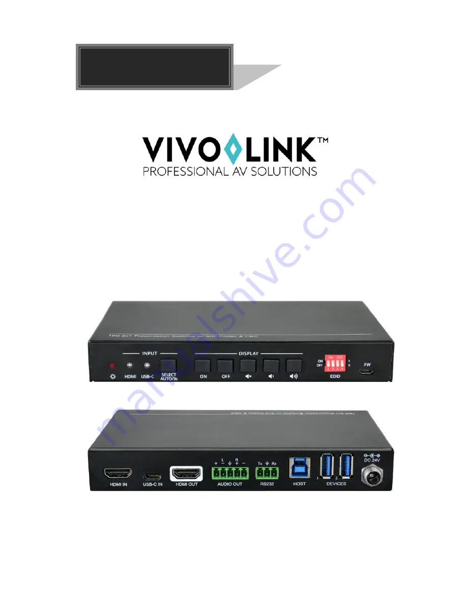
Page 9: ...the button to select the next input source or press and hold the button at least 3 seconds to enable auto switching mode Note that the factory default switching mode is AUTO DISPLAY D Press ON to turn on the display E Press OFF to turn off the display F Press to mute unmute display audio G Press to decrease the audio volume gradually or press and hold it to decrease the audio volume constantly H P...
Page 10: ...ed audio output RS232 3 pin terminal block to connect control device e g PC or third party device for RS232 control HOST Type B USB ports for host connection DEVICES Two type A USB ports to connect HID devices e g microphone and camera The HID devices are used to control the HOST when the HDMI input has been selected or to control the USB C source device e g Macbook when the USB C input has been s...
Page 11: ...sure all components and accessories included before installation System should be installed in a clean environment with proper temperature and humidity All of the power switches plugs sockets and power cords should be insulated and safe All devices should be connected before power on 4 2 System Diagram ...
Page 12: ...the SELECT AUTO 3s button at least three seconds again can exit AUTO mode but the input source will not be changed and the corresponding source LED will turns orange New input Upon detecting a new input the switcher will automatically select the new input Press the SELECT AUTO 3s button also can forcibly change the input source Reboot Once power is restored to the switcher it will automatically re...
Page 13: ...IP switch for specific video resolution and audio capabilities The switch represents 0 when in the lower OFF position and it represents 1 while putting the switch in the upper ON position Switch Status Video Resolution Audio Format 0000 Default EDID pass through 0001 1280x720 60Hz RGB 4 4 4 Stereo 0010 1920x1080 60Hz DVI 0011 1920x1080 60Hz 2D PCM 2 0 0100 1920x1080 60Hz RGB 4 4 4 Stereo 0101 1920...
Page 14: ... Software Installation Copy the control software file to the control PC Uninstallation Delete all the control software files in corresponding file path Basic Setting Connect the switcher with all input devices and output devices needed then to connect it with a PC which is installed with RS232 control software Double click the software icon to run this software Here take the software CommWatch exe...
Page 15: ...w Please set the parameters of COM number bound rate data bit stop bit and the parity bit correctly and then you are able to send command in command sending area Parameter configuration area Monitoring area show the commands and its feedback information Command sending area Operation area ...
Page 16: ...and are symbols for easy reading and do not need to be typed in actual operation Type the command carefully it is case sensitive 6 2 1 Device Control Command Function Feedback Example GET_FIRMWARE_VER SION Get the firmware version V1 0 0 FACTORY_RESET Factory reset FACTORY_RESET REBOOT System reboot REBOOT HELP Get the command details Example HELP SET_AV Feedback SELECT VIDEO AND AUDIO INPUT PORT ...
Page 17: ...tching status AUTO_SWITCH 1 AUTO_SWITCH 0 6 2 3 User define EDID There are five EDID values can be customized by sending the below command Command Function Operation UPLOAD_USER_EDID X X 1 5 represents the EDID its DIP switch status shows as below X DIP Switch Status 1 1011 2 1100 3 1101 4 1110 5 1111 Operation Step 1 Prepare the EDID file bin Step 2 Set the 4 pin DIP switch status for example 101...
Page 18: ...1 6 2 5 Switcher Baud Rate Setting Command Function Feedback Example SET_RS232_BAUD 0 Set the RS232 baud rate to 115200 RS232_BAUD 0 SET_RS232_BAUD 1 Set the RS232 baud rate to 57600 RS232_BAUD 1 SET_RS232_BAUD 2 Set the RS232 baud rate to 38400 RS232_BAUD 2 SET_RS232_BAUD 3 Set the RS232 baud rate to 19200 RS232_BAUD 3 SET_RS232_BAUD 4 Set the RS232 baud rate to 9600 RS232_BAUD 4 SET_RS232_BAUD 5...
Page 19: ... 02 38400 03 19200 04 9600 05 4800 06 2400 The T represents the delay time of sending command and its value is 00 99 The XXXX represents the specific command ASCII up to 48 byte Command SET_ON_05_30 1234567 Feedback BAUDRATE 4800 DELAY TIME 30 s DISPLAY ON TO SEND 1234567 SET_OF_ B _ T XXXX Send the command XXXX to the third party device while the DISPLAY OFF key is pressed The B represents the ba...
Page 20: ...te of third party device and its value is 00 06 the corresponding baud rate shows at above list The T represents the delay time of sending command and its value is 00 99 The XXXX represents the specific command ASCII up to 48 byte Command SET_AU_05_30 ABCDEFG Feedback BAUDRATE 4800 DELAY TIME 30 s VOLUME TO SEND ABCDEFG SET_AD_ B _ T XXXX Send the command XXXX to the third party device while the V...
Page 21: ...and CEC 17 7 Panel Drawing 18G 2x1 Presentation Switcher w Soft Codec CEC FW EDID ON OFF 1 0 1 2 3 4 OFF ON HDMI USB C SELECT AUTO 3s INPUT DISPLAY HDMI IN USB C IN HDMI OUT AUDIO OUT L R DEVICES 1 2 Tx Rx RS232 HOST DC 24V 24 5 mm 168 0 mm 95 0 mm ...
Page 22: ...cher is broken Send it to authorized dealer for repairing POWER indicator doesn t work or no respond to any operation Fail connection of power cord Make sure the power cord connection is good Static becomes stronger when connecting the video connectors Bad grounding Check the grounding and make sure it is connected well Cannot control the device by control device e g a PC through RS232 port Wrong ...
Page 23: ...mal wear and tear Use of supplies or parts not meeting our specifications No certificate or invoice as the proof of warranty The product model showed on the warranty card does not match with the model of the product for repairing or had been altered Damage caused by force majeure Servicing not authorized by distributor Any other causes which does not relate to a product defect Shipping fees instal...