VLHDMICTL1-MME
18G In-line HDMI Controller with Auto Display Control
All Rights Reserved
Version: VLHDMICTL1-MME_2019V1.1
User Manual
Page 1: ...VLHDMICTL1 MME 18G In line HDMI Controller with Auto Display Control All Rights Reserved Version VLHDMICTL1 MME_2019V1 1 User Manual ...
Page 2: ...t details FCC Statement This equipment generates uses and can radiate radio frequency energy and if not installed and used in accordance with the instructions may cause harmful interference to radio communications It has been tested and found to comply with the limits for a Class B digital device pursuant to part 15 of the FCC Rules These limits are designed to provide reasonable protection agains...
Page 3: ... to rain moisture or install this product near water Do not put any heavy items on the extension cable in case of extrusion Do not remove the housing of the device as opening or removing the housing may expose you to dangerous voltage or other hazards Install the device in a place with fine ventilation to avoid damage caused by overheat Keep the module away from liquids Spillage into the housing m...
Page 4: ...ion 5 4 2 System Diagram 5 5 DIP Switch Operation 6 5 1 EDID Management 6 5 2 HDCP Mode 8 6 System Control Setting 9 6 1 RS232 Command Setting 10 6 1 1 RS232 Control Software 10 6 1 2 Trigger Method Setting 11 6 1 3 CEC Control Setting 12 6 1 4 RS232 Control Setting 12 6 1 5 IR Control Setting 14 6 1 6 Relay Control Setting 15 6 1 7 System Command 16 6 2 Front Panel IR Learning 16 7 Panel Drawing ...
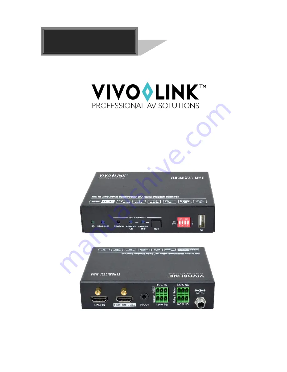
Page 5: ... by the 4 pin DIP switch on the front panel In addition the controller supports CEC pass through RS232 control IR learning and relay control 1 1 Features Supports up to 4Kx2K 60Hz 4 4 4 HDR10 and Dolby Vision HDCP 2 2 compliant HDCP pass through or converted to HDCP 1 4 for better compatibility Supports 4K to1080P down scaling Comprehensive EDID management with 8 EDID Options for various applicati...
Page 6: ...2 Relay 1 2 Control Connector 1 Type A USB 1 3 5mm mini jack 4 3 pin terminal blocks General HDMI Standard 2 0 HDCP Version 2 2 HDCP Pass through Supported CEC Control Supported Hot plug Supported Bandwidth 18Gbps HDMI Cable Length 1080P 60Hz 33 feet 10 meters 4K 60Hz 16 feet 5 meters Operation Temperature 5 55 Storage Temperature 25 70 Relative Humidity 10 90 Power Supply Input 100V 240V AC Outpu...
Page 7: ...s in IR learning mode and it will illuminate blue after successfully learning the IR command DISPLAY OFF LED The LED blinks blue when the controller is in IR learning mode and it will illuminate blue after successfully learning the IR command SET Press the button to enable IR learning mode Please refer to chapter 6 2 for more details 4 pin DIP switch for EDID setting and HDCP mode selection FW Typ...
Page 8: ...IR emitter to send IR signal RS232 3 pin terminal block to connect the RS232 control device e g PC or a device e g projector to be controlled by RS232 commands Sensor 3 pin terminal block to connect external sensor or switch Relay 1 2 Two 3 pin terminal blocks to connect projection screen for relay control DC 5V DC connector for the power adapter connection DC 5V NO C NC RS232 Sensor Relay 1 Relay...
Page 9: ...stallation System should be installed in a clean environment with proper temperature and humidity All of the power switches plugs sockets and power cords should be insulated and safe All devices should be connected before power on 4 2 System Diagram The following diagram illustrates typical input and output connections that can be utilized with this controller ...
Page 10: ...ion and it represents 1 while putting the switch in the upper ON position Switch 1 3 are used for EDID setting The DIP switch status and its corresponding setting are shown at the back of the product Switch Status Video Resolution Audio Format 000 Pass Through 001 1080P 2CH 010 1080P Multi CH 011 3840x2160 30Hz HDR 2CH 100 3840x2160 30Hz HDR Multi CH 101 3840x2160 60Hz HDR 2CH 110 3840x2160 60Hz H...
Page 11: ...e controller to the PC with USB cable and then power on the controller the PC will automatically detect a virtual disk named of BOOTDISK 3 Double click to open the disk a file named of READY TXT will be showed 4 Copy the user defined EDID to the BOOTDISK disk 5 Reopen the disk to check the filename READY TXT whether automatically becomes SUCCESS TXT if yes the user defined EDID was imported into t...
Page 12: ...or to OFF for HDCP Passive mode Switch Status Mode HDCP OFF 0 Passive Default Automatically follows the HDCP version of source device ON 1 Active If the input video has HDCP content the HDCP version of HDMI output is HDCP 1 4 for broader video solution If the input video has no HDCP content the HDMI output has no HDCP either ...
Page 13: ... Toggle the state of relay 1 as follow I O State Relay State NO NC On Closed Closed Open Off Open Open Closed SYSTEM OFF When the controller detects all input source devices are removed or not receives IR signal within the delay time default 10mins range of 5mins 180mins the system will off and automatically perform the below actions at the same time Send CEC OFF to turn off display Send RS232 OFF...
Page 14: ... Software Installation Copy the control software file to the PC which is connected to the controller Uninstallation Delete all the control software files in corresponding file path Here take the software CommWatch exe as example Double click the following icon The interface of the control software is shown as below Parameter configuration area Monitoring area indicates if the command sent works Co...
Page 15: ...etects IR or video signal SYSONMETH1 SET DETECT VIDEO TRIGGER SYSOFFMETH X Set the trigger method to perform SYSTEM OFF X Description 0 Detects no IR signal 1 Detects no HDMI video signal default 5V or TMDS 2 Detects no IR and video signal SYSOFFMETH1 SET NOT DETECT VIDEO TRIGGER NOSIGDLY XXXXX Set the system off time to xxxxx default 10mins range of 5mins to 180mins When no HDMI video signal has ...
Page 16: ...GNAL DELAY TIME 300S GNOIRDLY Report the delay time of SYSTEM OFF when the controller detects no IR sensor signal DETECT NO IR DELAY TIME 300S G5VORTMDS Report the detection method of input source 5V TMDS DETECT INPUT SOURCE USE 5V 6 1 3 CEC Control Setting Command Function Feedback Example CECON Enable CEC OPEN CEC FUNCTION CECOFF Disable CEC CLOSE CEC FUNCTION GCECSTAUS Report CEC status CEC FUN...
Page 17: ... to the third party device e g Projector whose baud rate is X RS232OFF 3 30 31 32 Send the HEX command 30 31 32 to the third party whose baud rate is 9600 RS232U X XXX Set the user defined ASCII command to send to the third party device e g Projector whose baud rate is X RS232USER 3 123abc Send the user defined command 123abc to the third party whose baud rate is 9600 RS232U X XXX Set the user def...
Page 18: ...Y IR USER IRSTUDY0 READY STUDY IR DISPLAY OFF PLEASE REMOTE CONTROL RECEIVER IN 10S IRSEND X Send the learned IR command X Description 0 SEND IR DISPLAY OFF 1 SEND IR DISPLAY ON 2 SEND IR USER IRSEND0 SEND IR DISPLAY OFF IRDLY XXX Set the sending interval time between IR ON and IR USER to XXX default 3s range of 1S to 180s IRDLY 003 SET DELAY TIME BETWEEN IR ON AND IR USER 3S IRPCS X Set the sendi...
Page 19: ...ELAY 2 TIME DELAY TIME 10S GRELAY1COT Report Relay 1 delay time RELAY 1 TIME DELAY TIME 10S GRELAY2COT Report Relay 2 delay time RELAY 2 TIME DELAY TIME 10S Relay Port Definition When the controller start SYSTEM ON the Relay 1 port will perform the below actions 1 The NO connection closes and NC connection opens 2 When the delay time is up the NO connection opens and NC connection closes When the ...
Page 20: ...ommands from IR remote Step 1 Press SET to choose DISPLAY ON or DISPLAY OFF command to be set DISPLAY ON LED Flashing indicates that DISPLAY ON mode is selected DISPLAY OFF LED Flashing indicates that DISPLAY OFF mode is selected Step 2 Point the IR remote at the SENSOR and press the respective button on the IR remote Step 3 The DISPLAY ON or DISPLAY OFF LED will stop flashing and remain lit to in...
Page 21: ...with Auto Display Control 17 7 Panel Drawing DC 5V NO C NC RS232 Sensor Relay 1 Relay 2 12V Sig HDMI IN Tx Rx NO C NC HDMI OUT CEC 84 0mm 120 0mm 28 0mm HDMI OUT FW ON OFF 1 0 1 2 3 4 IR LEARNING DISPLAY ON SENSOR SET DISPLAY OFF ...
Page 22: ...itcher while local input is in normal working state Splash screen in output devices Poor quality of the connecting cable Change for another cable of good quality Cannot control this controller by control device e g a PC through RS232 port Wrong RS232 communication parameters Make sure the RS232 communication parameters are correct This switcher is broken Send it to authorized dealer for repairing ...
Page 23: ...mal wear and tear Use of supplies or parts not meeting our specifications No certificate or invoice as the proof of warranty The product model showed on the warranty card does not match with the model of the product for repairing or had been altered Damage caused by force majeure Servicing not authorized by distributor Any other causes which does not relate to a product defect Shipping fees instal...