I
NSTALLATION
4
C
HAPTER
2
2.4
C
ONNECTIONS
2.4.1 G
ENERAL
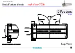
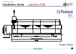
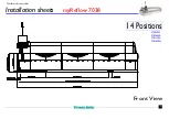
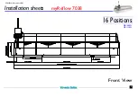
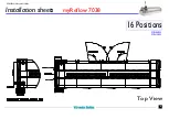
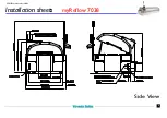
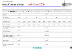
See for connection specifications the “install sheet” at the end of this chapter.
2.4.2 E
LECTRICAL
CONNECTION
Only qualified electricians should work on the electrical circuits of the machine.
1.
Connect the mains leads in accordance with the diagrams.
Check the Current rotation of the phases. The current rotation of the phases L1, L2, L3 must be
clockwise.
2.
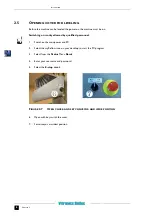
Block the mainswitch in the “OFF” position with a padlock to prevent dangerous situations.
2.4.3 N
ITROGEN
CONNECTION
1.
Connect the supply hose to the hose connector at the infeed side of the machine.
2.4.4 E
XHAUST
SYSTEM
One exhaust gauge of 165 mm (6.5”) is provided. This should be connected with the customer’s
exhaust system (not supplied by Vitronics Soltec).
•
Inflammable and/or explosive gas might develop in the machine because of the evaporation of
the solvent in the flux.
•
An exhaust system that functions well, will bring the gases below the explosion concentra-
tions.
•
It is therefore necessary to have a sufficient exhaust in the machine.
•
The exhaust system also has to be checked continuously on its well functioning.
•
The machine is prepared to interfere in the E-stop circuit of the machine with a potential free
contact of the exhaust system. This contact has to be normally open, and therefore closed
when the exhaust functions well (fail safe).
NEVER USE THE MACHINE WITHOUT THE EXHAUST SYSTEM
.
Summary of Contents for 42284
Page 4: ...iv...
Page 8: ......
Page 24: ...INSTALLATION 8 CHAPTER 2 2 7 INSTALLATION SHEETS AND REQUIREMENTS see next pages...
Page 25: ...1 Installation sheets 10 Positions Front View MR820A myReflow 7038 VERSION November 2009...
Page 26: ...2 Installation sheets myReflow 7038 VERSION November 2009 Top View 10 Positions MR820A...
Page 33: ...9 Installation sheets myReflow 7038 VERSION November 2009 Side View...

