background image


12 

1.4


Microscope Focus   

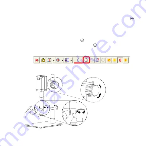
Move  the  CSZ064C  upward,  leave  82mm  to  the  object;  press  Zoom  out 


button to move the sensor to end position.    Rotate the optical zoom from 0.6x-4x 
see if all image is clear.    If the lens  does not reach parfocal distance, try turning 
the  gearbox  to  find  clear  image.    If  focus  lost,  please  refer  to  the  instruction  to 
tuning parfocal distance.     

(2-1)


In HDMI mode, press Zoom Out 

  till the end.   

(2-2)


In  PC  CAM  mode,  press  the  Zoom  Out 

  till  the  end.  (The  sensor 

position at around 18XX, each device has a little difference due to  the 
assembling tolerance.   


When the image sensor position is fixed, as in (2-1) and (2-2), focus the image 
by using knob 

j

  to adjust the height and knob 

k

  to fine tune. 


l


k


Summary of Contents for UM06-CSZ064C

Page 1: ...UM06 CSZ064C User s Guide Version 1 0A...

Page 2: ......

Page 3: ...n 2 1 1 Packing Contents 2 1 2 IR remote controller 2 1 3 Microscope introduction 7 1 4 Microscope Focus 12 1 5 Microscope accessory 14 2 Printed Notice 15 2 1 Maintenance 15 2 2 Product Specification...

Page 4: ...ontroller 1 2 1 Buttons for Common Use The following buttons are used for both PC Cam and HDMI mode 1 Power Turn on off 2 Motor Reset Recalibrates entire operation Returns to the lens position If a lo...

Page 5: ...3 3 1 Zoom in Zooms in speed increases when held 3 2 Zoom out Zooms out speed increases when held Microscope remote controller Buttons for common use...

Page 6: ...ing buttons are used only for PC Cam mode 1 PC CAM When in PC CAM mode the USB cable must connect to a PC and microscope Please disable software before switching to HDMI mode or powering off Buttons f...

Page 7: ...tween bright and dark 1 31 2 3 SATURATION Adjusts the color level 1 31 2 4 EXPOSURE VALUE ON Auto mode use with the exposure value This mode will automatically adjust the image brightness For the best...

Page 8: ...em 4 Down Choose the next item 5 Left Choose the next value 6 Right Choose the last value 7 Exposure Value 13 levels of exposure value are selectable from 0 2 2 0 7 1 Increase Use to increase exposure...

Page 9: ...the image press the button again to return to preview 12 Sharpness On Off sharpness mode Please refer to Section 1 2 3 2 1 3 Microscope introduction 1 3 1 IR Remote Area Indicator When both the HDMI...

Page 10: ...dicator will blink if the indicator did not blink means the signal was not delivered and please repress again 2 HDMI indicator b When lit up the device is in HDMI mode 3 USB indicator c When lit up th...

Page 11: ...in the box 2 USB e The USB cable is used to connect the microscope to a PC to access the application program When the device is in PC Cam mode connect the microscope to a PC through the USB cable from...

Page 12: ...cope to the screen using the HDMI cable from the box For TV screen connections make sure to choose the homologous image ratio and format 1 3 3 CSZ064C Lens Assembling Each CSZ064C lens has reach its p...

Page 13: ...11 1 3 4 Illuminance CSZ064C Lens has its own Coaxial illuminance please insert the coaxial light i to lens then switch power ON j h i j...

Page 14: ...ng the gearbox to find clear image If focus lost please refer to the instruction to tuning parfocal distance 2 1 In HDMI mode press Zoom Out till the end 2 2 In PC CAM mode press the Zoom Out till the...

Page 15: ...rect User s must create and calibrate a new scale Refer to the AP User s Guide in CD for more detailed information on create a new scale file CSZ064C Zoom lens working distance 82mm 3 228 CSZ064C Lens...

Page 16: ...m please refer to the AP manual for more information The calibrator is transparent and can be applied onto the object directly 1 5 2 White balance card The white side is used to calibrate the white ba...

Page 17: ...unction if it encounters strong collision vibration or distortion 2 1 4 Turn the microscope off before cutting off the power supply do not forced cut off the power supply 2 1 5 Do not face the lens ag...

Page 18: ...P 1920 1080 Pixel image USB port USB 2 0 3 0 compatible connect with PC Focus control IR remote controller PC application program control Power supplier adaptor input DC 5 0V 2 0A input AC 100 240V 50...

Page 19: ...e the device or the device is dropped or damaged please switch off and remove the power supply to avoid fire and electric shock Do not look steadily into Light sources after switching on the host as i...

Page 20: ...d fittings such as the power supplier USB cable HDMI cable calibrator white balance card remote controller etc Services caused by any of the following situations in the period of the warranty shall no...

Page 21: ......

Page 22: ...el no S L nos Purchase d a t e DD MM YYYY Purchaser T e l n o A d d r e s s Email Distributor Seal for Confirmation Stamp is necessary for validation of the Warranty Distributor s seal shall include n...

Page 23: ......

Page 24: ...HTTP WWW VITINY COM MicroLinks Technology Corp All rights reserve...

Reviews: