VT5000ES48
Lithium Battery
Product Manual
ViTech Power Systems
5/364 Park Road, Regents Park, NSW 2143
1300 699 669
www.
vitechpower.com.au
Version:1.1 (22/09/2020)
Page 1: ...VT5000ES48Lithium Battery Product Manual ViTech Power Systems 5 364 Park Road Regents Park NSW 2143 1300 699 669 www vitechpower com au Version 1 1 22 09 2020 ...
Page 2: ... 4 Port RS485 and RS232 12 3 INSTALLATION 13 3 1 DC CABLE REQUIREMENTS 13 3 2 DC CABLE 13 3 2 1 Material List 13 3 2 2 Steps 13 3 3 DC CABLE CONNECTION 14 3 3 1 Single Unit 14 3 3 2 Multi Units in Parallel 4 sets as an example 15 3 3 3 Method to set up Master Pack and Slave Pack 16 4 POWER ON AND OFF 17 4 1 INSTRUCTION 17 4 1 1 System Power ON 17 4 1 2 System Power OFF 17 4 1 3 Sleep and Wake up F...
Page 3: ... self monitoring function for the detection of any abnormalities in energy storage n Compact Design The height is nicely designed in 3U in favor of standard industrial applications n High Scalability Multiple energy storage modules can be connected in parallel and the capacity can be customized according to the intended use 1 2 Safety Precautions ViTech Power products are designed with full consid...
Page 4: ... fire 2 Insert the connector of the communication cable all the way in If it is connected improperly the system may be deactivated n Prohibited Do not install in a closed area If the module controller is installed in a closed area with no air conditioning heat may build up inside the set and cause a fire n Prohibited Do not place the set in direct sunlight or near a heater Doing so can cause defor...
Page 5: ... space 2 Remove any dust buildup in the vent 3 Do not place the set upside down or sideways 4 Do not place on a shag carpet or bed 5 Do not cover the vent with a cloth etc n Instruction Install in a stable place 1 If you install the set in an unstable place such as an unstable rack it may fall and cause injury 2 Do not install upside down or sideways The set may drop and cause injury n Instruction...
Page 6: ...emove the power connector from the POWER CONNECTOR terminal of the module n Prohibited Do not put anything stand or sit on the set If you put anything on the set it may fall and cause injury Also if it is used as a stool for example it may topple and cause injury n Instruction Follow related laws or ordinances for disposal When you dispose of this product do not dispose as general or household was...
Page 7: ... short even from fully charged DO NOT n Disassemble n Modify the product Modification may destroy the protection function inside or cause abnormal charge discharge heat generation gas eruption or fire n Touch the rear output terminal except for installation n Throw the product into fire or heat or otherwise expose the set to heat or naked flame n Submerge the product in liquid or allow it to becom...
Page 8: ...each 1P8S lithium cell module there are 8 pcs of 100 Ah LFP cell The overall system also provides standard communication port i e CAN and RS485 to monitor the working status and communicate with upper machine as well as the Power Conversion System PCS in front The system schematic drawing is presented in Figure 1 Website www vitechpower com au ...
Page 9: ...Rated Voltage V 51 2 Rated Capacity Ah 100 Rated Energy kWh 5 12 Packing 1P16S Working Voltage Range V 44 8 57 6 Standard Charging Current A 50 Max Continuous Charging Current A 50 Standard Discharging Current A 50 Standard Charging Method 0 5C CC to 57 6V CV at 57 6V till current is 0 05C Working Temp C Charging 0 50 Discharging 20 55 Working ROH 20 80 Storage Temp C 20 50 Website www vitechpower...
Page 10: ...lowed Refer to our Energineer 2 4 1 Definition of Voltage Sampling Connector PIN Wire No Signal Wire size mm Remarks 1 B0 Signal 0 3 Cell 1 2 B2 Signal 0 3 Cell 2 3 B4 Signal 0 3 Cell 4 4 B6 Signal 0 3 Cell 6 5 B8 Signal 0 3 Cell 8 6 B10 Signal 0 3 Cell 10 7 B12 Signal 0 3 Cell 12 8 B14 Signal 0 3 Cell 14 9 B16 Signal 0 3 Cell 16 10 NC NC NC NC 11 B1 Signal 0 3 Cell 1 12 B3 Signal 0 3 Cell 3 13 B5...
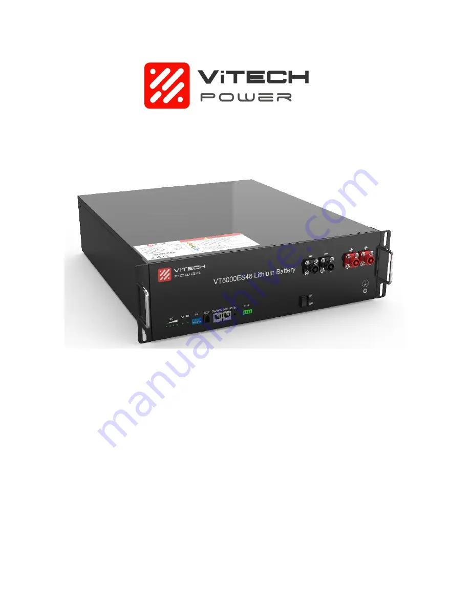
Page 11: ...p 4 2 4 3 Front View Figure 3 Front View of VT5000ES48 Item Name Model Remarks 1 SOC LED x4 2 Alarm LED 3 RUN LED 4 Dialer 5 Communication port RJ11 RS232 To upper machine 6 Communication port 2 RJ45 CAN To PCS RS485 Internal Connection 7 Reset Waken system from malfunction status 8 Dry Contact 9 Power On Off Switch 10 Port Negative x2 PSR6XAB Black 5 7 25 mm2 11 Port Positive x2 PSR6XBB Orange 5 ...
Page 12: ...tions Description CAN Pin 1 CAN H Pin 5 CAN L Pin 2 3 4 6 7 NC Pin 8 GND RS485 Pin 1 4 5 NC Pin 2 7 RS485 A Pin 3 6 RS485 B Pin 8 GND RS232 Pin 1 2 6 NC Pin 3 BMS transmit Computer receiver Pin 4 BMS receiver Computer transmit Pin 5 GND Website www vitechpower com au ...
Page 13: ... 1 Material List Plug Isolation Cap Tail hood 3 2 2 Steps 1 Put wire through isolation cap and Tail Hood 2 Swipe outer isolation layer of DC cable DC cable must be a multicore wire Caution n Turn off system before doing electrical connection n Ensure all the cables are in electrical safe condition Danger Website www vitechpower com au ...
Page 14: ...ched at the terminal using a wire clamp 4 Tighten the isolation cap and plug contact 5 Put the positive and negative plug on to the system and tighten it 6 Use isolation cap for unused DC plug 3 3 DC Cable Connection 3 3 1 Single Unit Figure 5 Single Unit Connection Website www vitechpower com au ...
Page 15: ... Master Pack and Slave Pack VT5000ES48 can be used as single unit as well as multi units in parallel mode The customer must inform supplier if multi units mode is required The Master Pack can be used individually but Slave Pack cannot be used individually Website www vitechpower com au ...
Page 16: ...16 3 3 3 Method to set up Master Pack and Slave Pack Figure 7 Dial Diagram Master Slave machine dial code diagram Website www vitechpower com au ...
Page 17: ...d Wake up Function Number Sleep Condition Wake up Condition Mark 1 Forced sleep by upper computer Reset button 2 Forced sleep by soft switch Soft switch Only those equipped with soft switch can pass the call Wake up 3 Total Voltage is lower than 48V or monomer is lower than 2 8V and continuous No charge and discharge current for 4 hours no communication goes to sleep Reset button Soft switch Commu...
Page 18: ...kle 1 Twinkle 2 Discharging Normal Continuous no Real SoC Warning Continuous Twinkle 3 Overcharging ALM no Over discharging Twinkle 1 no Overheat Low Temp Over current Shortcut Twinkle 1 Twinkle 2 Malfunction Warning no Continuous no no no no BMS Damage MOS Damage Temp sampling malfunction 4 1 6 LED Twinkle Status Status On Off Twinkle 1 0 25s 3 75s Twinkle 2 0 5s 0 5s Twinkle 3 0 5s 1 5s 4 1 7 So...
Page 19: ...wer shall not be liable n It should be stored in 60 SoC status n It should be stored at ventilation environment Temp 35 C ROH 65 n It should be stored avoiding humid condition n It should be stored in place where they can be monitored by professionals 6 Disclaimer It should be noted that ViTech Power shall not be liable if any necessary materials are added to this user s manual without further inf...
Page 20: ...20 Website www vitechpower com au ViTech Power Systems 5 364 Park Road Regents Park NSW 2143 1300 699 669 www vitechpower com au Version 1 1 22 09 2020 ...