WPRP-1 Installation Guide – Version 2.00
WPRP-1 Installation Guide
WPRP-1 Installation
1.
Determine the installation location for the WPRP-1 device. Consider the following when determining the installation location:
Standard WPRP-1 device is equipped with AC to DC power adaptor and require a standard 110VAC or 220VAC power outlet.
The power adaptor consists of 6’ DC power cable and 6’ of AC power cord. Consider these cable lengths and the distance
between the power outlet and the WPRP-1 device.
2.
Position the WPRP-1 device on the mounting surface and confirm that it is vertical to the floor.
Note: When the device is installed properly, the LED should be on the left top corner (front view).
3.
Secure the WPRP-1 device to the wall using screws appropriate for the mounting surface (use 1.5”-2” long screws).
4.
Connect the external antenna (2.5db or 3db gain) to the BNC connector.
5.
Connect the output devices to their respective port. Below are the available connector types that may be installed on your
device:
6.
Connect the power adaptor male connector to the POWER port of the WPRP-1 device.
Note: The WPRP-1 devices should be protected from direct rain and snow, and if possible, from direct sun. These devices are
suitable for outdoor installation. Yet, the devices are not watertight and it’s highly recommended that outdoor installation locations
will include an overhang to protect the WPRP-1 device from direct rain, snow and sun.
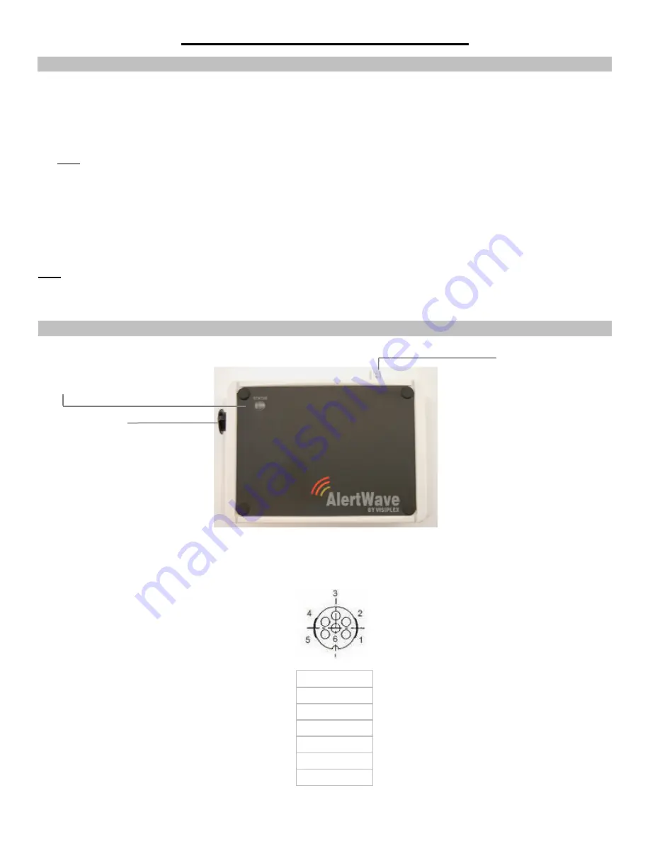
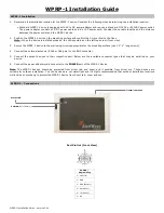
WPRP-1 – Connections
Port Pin Out (Front View)
POWER /
Programming
1 – VDC (IN)
2 – GND
3 – GND (Battery)
4 – RX (RS232)
5 – TX (RS232)
6 – N.C.
POWER (6 Pin Female)
Transmit Antenna
Status LED


