


D
UET
E-2/DuetD-2 U
SER
M
ANUAL
C
ONFIGURATION
Visionary, Network Audio Video
16
C
ONFIGURATION
C
ONFIGURING
E
NCODER AND
D
ECODER
IP
A
DDRESSES
As previously mentioned, by default, the encoders and decoders are shipped from the factory in DHCP mode with Auto IP Failover.
For a permanent installation, and to ensure system consistency, it is recommended to configure all of the encoders and decoders
with static IP addresses.
Important
: IP configuration changes must be done correctly to avoid any communication disruptions with the units. Communication
with the Vision Lite Server and the computer that the application resides on is dependent upon the computer being in the same IP
address range as the encoders and decoders on the network. Therefore, before making any IP address changes to the units, we
recommend having two statically-assigned IP addresses on the computer.
When using DHCP, configure the first static IP address to an address within the defined DHCP range for your network (the subnet
(VLAN) defined by the DHCP netmask for your network). Be sure that the static address you assign is not in the range of addresses
that will be given out by the DHCP server to avoid address conflicts. For example: If the DHCP range = 192.168.1.100 – 192.168.1.150
and netmask = 255.255.255.0, you can assign 192.168.1.151.
When using Auto IP, assign an address within the range of 169.254.1.0 – 169.254.254.255, with a 255.255.0.0 subnet mask.
AND
Configure a second static IP address in the range of the IP addresses you are planning to assign to the units.
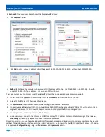
Assign new IP addresses to the encoder and decoder units as follows:
1. Access the web interface for the encoder or decoder unit.
2. Log in with
username=
admin
password
=admin.
3. Click the
Network
tab.
4. Set
IP.MODE
to
Static
.
5. Set the
IP.ADDRESS
. Example: 192.168.1.45
6. Set the
IP.NETMASK
. Example: 255.255.255.0
7. Set the
IP.GATEWAY
. Example: 192.168.1.1
8. Set the
IP.DNS_SERVER
(optional). Example: 4.2.2.1
9. Click
Save
to save the new settings. The unit will automatically reboot.
The unit is now configured with the new network settings.
V
LAN
T
RUNK
M
ODE
The Duet-2 utilizes a single physical network interface for audio, control, and video. To separate the AV stream from the Dante
network audio, and control data, the Duet-2 is capable of enabling its network interface as a trunk port. This allows for tagging the
AV stream traffic for one VLAN and tagging the Dante network audio for a separate VLAN.
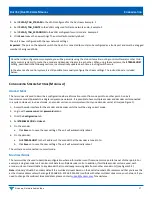
Enabling VLAN trunk mode for Duet-2 as follows:
1. Access the web interface for the Duet-2 unit.
2. Log in with
username
=admin
password
=admin
3. Click the
Network
tab
4. Set
VLAN.TRUNK_MODE
to
TRUE