pictor M1817
Commissioning
41
999.994.528.10-en-1.4
© Vision & Control GmbH 2014
7.3.6 Connecting the video cable
Perform the following steps only in de-energiesed state:
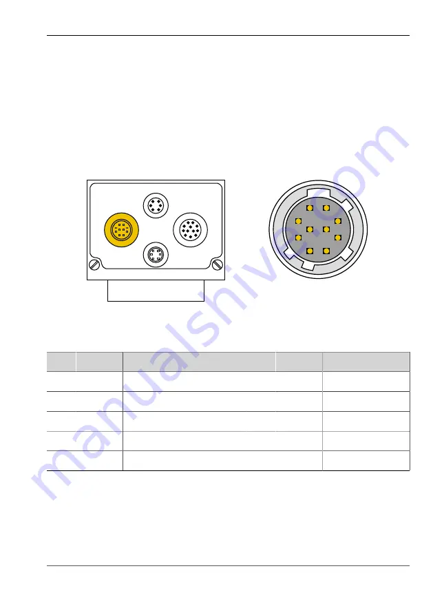
1. Insert the 10-pin Hirose plug of the video cable into the video socket on the
device.
2. Connect the 15-pin D-Sub plug with a monitor.
Video
LAN
Trig.
I/O
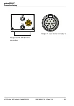
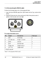
Image 14: Video cable connection
9
8
7
6
5
4
3
2
1
10
Image 15: View: socket on camera
Pin assignments video cable
Pin Signal
Description
Pin Signal
Description
1
G GND Ground signal green
2
G OUT
Signal green
3
R GND
Ground signal red
4
R OUT
Signal red
5
VS GND Ground Vertical Sync
6
VS OUT Vertical Sync
7
HS GND Ground Horizontal Sync
10
HS OUT Horizontal Sync
8
B GND
Ground signal blue
9
B OUT
Signal blue
Table 15: Pin assignments video cable
Summary of Contents for 4-20-327
Page 62: ......


