


Manual BG41/BG42/BG43
List of figures
Rev. 99/49
A-1
Appendix
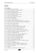
A List of figures
Fig. 1-1: Deliverable interface building blocks ................................................................................ 1-4
Fig. 2-1: Data transfer via interface ( Example Module BG41) ....................................................... 2-1
Fig. 2-2: Front panel of building block BG41 .................................................................................. 2-2
Fig. 2-3: Position of jumpers and DIL switches on BG41................................................................ 2-3
Fig. 2-4: Front panel of building block BG42 .................................................................................. 2-4
Fig. 2-5: Position of Jumpers and DIL switches on BG42 ............................................................... 2-5
Fig. 2-6: Front panel of building block BG43 .................................................................................. 2-6
Fig. 2-7: Position of jumpers and DIL switches on BG43................................................................ 2-7
Fig. 2-8: Firmware block diagram BG43.......................................................................................... 2-9
Fig. 2-9: Firmware’s memory distribution........................................................................................ 2-9
Fig. 3-1: Structure of the 20mA current loop-moduls ...................................................................... 3-4
Fig. 3-2: Allocation of terminal pins when operating 20mA current loop modules......................... 3-5
Fig. 3-3: Characteristic curves of the current sources in relation to the applied voltage.................. 3-6
Fig. 3-4: An active 20mA current loop interface.............................................................................. 3-7
Fig. 3-5: A passive 20mA current loop interface.............................................................................. 3-8
Fig. 3-6: The structure of the RS232C modules ............................................................................... 3-9
Fig. 3-7: Allocation of terminal pins when operating RS232C modules.......................................... 3-9
Fig. 3-8: RS232C interface : connection with a RTS/CTS handshake........................................... 3-10
Fig. 3-9: RS232C interface: connection without a handshake........................................................ 3-11
Fig. 3-10: Structure of a 20mA current loop/RS232C combination module.................................. 3-12
Fig. 3-11: Allocation of terminal pins when using a 20mA Current Loop Module ...................... 3-13
Fig. 3-12: Allocation of terminal pins when using a RS232C-module ......................................... 3-13
Fig. 3-13: Structure of the RS422/RS485 module.......................................................................... 3-14
Fig. 3-14: Allocation of terminal pins when using a RS422/RS485-moduls ................................ 3-15
Fig. 3-15: Point to point connection with a RS422/RS485-module ............................................... 3-16
Fig. 3-16: Two-wire connection with a RS422/RS485 module ..................................................... 3-17
Fig. 3-17: Multidrop connection with a RS422/RS485 module ..................................................... 3-18
Fig. 3-18: Four-wire connection with a RS422/RS485 module ..................................................... 3-19
Fig. 3-19: Structure of RS422P and RS485P modules ................................................................... 3-20
Fig. 3-20: Allocation of terminal pins when using RS422P and RS485P modules ...................... 3-21
Fig. 3-21: Two-wire bus connection............................................................................................... 3-21
Fig. 3-22: Structure of the CENTRONICS module........................................................................ 3-22
Fig. 3-23: Allocation of terminal pins when using a CENTRONICS module .............................. 3-23
Fig. 3-24: Point-to-point connection when using a CENTRONICS module ................................. 3-23
Fig. 3-25: Structure of an SSI module ............................................................................................ 3-24
Fig. 3-26: Data flow........................................................................................................................ 3-25
Fig. 3-27: Allocation of the terminal pins when using an SSI module........................................... 3-26
Summary of Contents for SSM-BG41
Page 2: ...Lerrzeichen...
Page 8: ...Contents Manual BG41 BG42 BG43 iv Rev 99 49...
Page 10: ......
Page 16: ......
Page 26: ...Firmware s memory distribution Manual BG41 BG42 BG43 2 10 Rev 99 49...
Page 28: ......
Page 53: ...Manual BG41 BG42 BG43 Interface modules Rev 99 49 3 25 3 2 7 2 Data flow Fig 3 26 Data flow...
Page 114: ...Functional description and allocation of terminal pins Manual BG41 BG42 BG43 3 86 Rev 99 49...
Page 116: ......
Page 215: ...Manual BG41 BG42 BG43 Software Rev 99 49 4 99 Month 06h Year 95h Weekday Tuesday 02h...
Page 222: ...Application of interfaces without data handling blocks Manual BG41 BG42 BG43 4 106 Rev 99 49...
Page 224: ......
Page 258: ...Structure guidelines Manual BG41 BG42 BG43 5 34 Rev 99 49...
Page 260: ......
Page 274: ...Overview cycle load Manual BG41 BG42 BG43 6 14 Rev 99 49...
Page 275: ...Appendix A List of figures A 1 B Index of tables B 1 C Index C 1...
Page 276: ......
Page 280: ...List of figures Manual BG41 BG42 BG43 A 4 Rev 99 49...


