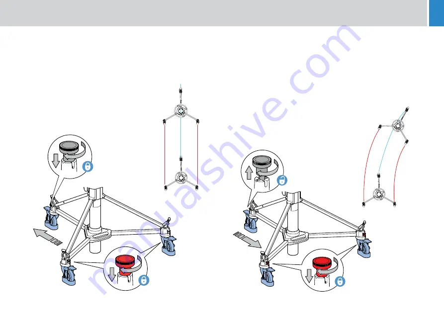
background image

19

Tracking motion 

(Track Lock)

For tracking motion, engage all three track locks. 

The skid can now track backwards and forwards in a straight line.

Steer motion

 (Steering Traveling)

For steer motion:

Position the skid so that the fixed leg (with the grey knob) is in the 

direction of travel.

Disengage the grey track lock.

Engage the red track locks.

With the fixed leg of the skid facing forwards 


the skid can now be moved with a  

‘steering type’ motion.

Operation

All Wheels Track-

locked to a single 

direction


One wheel free roation, 

two track-locked 

towards free wheel

Summary of Contents for OSPREY lite

Page 1: ...User Guide Pedestal Part No V4169 0001 EN www vinten com Osprey Lite Pedestal ...

Page 2: ...changes Changes will be incorporated in new versions of the publication We are making every effort to ensure that our publications are updated on a regular basis to reflect changes to product specifications and features Should this publication not contain information on the core functionality of your product please let us know You may be able to access the latest revision of this publication from ...

Page 3: ...essurizing the pedestal 11 Pressurizing the pedestal using a portable pump 13 Pressurizing from an external pressure source 14 Fitting and balancing the load 15 Operation 16 Height adjustment 16 Lower stage 16 Top stage 16 Brakes 17 Cable guards 17 Pedestal movement 18 Castor motion 18 Tracking motion 19 Steer motion 19 Transportation and storage 20 Servicing 21 Cleaning 21 Maintenance 21 Routine ...

Page 4: ...le and open book symbols it is imperative that you consult this operators guide before using this pedestal or attempting any adjustment or repair WARNING Before fitting adjusting or removing the payload the elevation column must be lowered to a safe working height and wheel brakes must be applied WARNING An abnormal or unbalanced payload can cause the product to become unstable Strictly adhere to ...

Page 5: ...ure and dust WARNING The product should not be used outside the operating temperature limits Refer to the product technical specifications for the operating limits for the product CAUTION Do not use solvent or oil based cleaners abrasives or wire brushes Clean with a dry lint free cloth WARNING The fitting of non approved parts or accessories or the carrying out of non approved alterations or serv...

Page 6: ...levision camera operators WARNING Do NOT attempt to use this product if you do not understand how to operate it Do NOT use this product for any other purpose than that specified in the Usage statement above Maintenance beyond that detailed in this Operators Guide must be performed only by competent personnel in accordance with the procedures About this Guide This operators guide is issued for the ...

Page 7: ...5 Components and Connections Box Contents 1 Osprey Lite 2 Manual Pump 1 2 ...

Page 8: ...onents and Connections 1 Adaptor retaining bolts 2 Control valve 3 Safety catch 4 Tank assembly 5 Elevation tube 6 Velcro strap 7 Foot support and strap 8 Track locking pin 9 Brake 10 Fixed leg 11 Skid clamp ...

Page 9: ...2 Skid centre casting 13 Folding leg 14 Cable guard 15 Cable guard adjustment knob 16 Outer tube 17 Strut 18 Bottom clamp 19 On shot clamp 20 Steering ring 21 Schrader valve and cap 22 Pressure gauge 23 QR code information portal 3 ...

Page 10: ... tracking skid adaptor V4169 2006 2 200mm Hi Hat 3155 3B 3 150mm Bowl Adaptor 3330 17 4 Heavy Duty Quick Fix adapter 3490 3 5 Mitchell head Adaptor 3055 3B 6 Tracking Dolly Skid 3369 57 7 Base Adaptor 08349 8 PTZ and Prompter plate V4166 1002 9 100mm Bowl Adaptor 3330 16 1 2 3 4 5 9 6 7 8 ...

Page 11: ...n the skid upside down depress the leg locking plungers 1 and swing each folding leg 2 out until the plungers lock the legs in the fully open position 2 Set the skid on the ground on its wheels and apply the wheel brakes 3 by pressing down 2 3 2 ...

Page 12: ...o the skid centre casting ensuring skid clamp 1 is aligned with fixed leg on the skid see marking on skid for correct orientation at the same time engaging the struts 4 on the foot supports 6 7 Secure each strut to the foot support with the rubber strap 8 Tighten the skid clamp 1 using moderate hand pressure only The clamp lever has a spring loaded ratchet type action and is operated as follows 9 ...

Page 13: ...1 bar 160 psi Do not pressurize the pedestal beyond the maximum safe working pressure indicated by the leading edge of the red sector on the gauge The pedestal s fitted with a pressure relief valve as a safeguard against over pressurization Do not attempt to adjust the pressure relief valve WARNING A pressurized pedestal will rise rapidly when safety catch is released Do not release safety catch w...

Page 14: ...n pump proceed as follows 1 Push the control valve 1 in and turn 90 clockwise and release pause for 5 seconds 2 Push the control valve 1 in and turn a further 90 to the PUMP position and release 3 Ensure that the bottom clamp 2 is engaged Remove the payload if fitted 4 Slacken the on shot clamp 3 5 Push down on the steering ring 4 against any residual pressure and release the safety catch 6 Set th...

Page 15: ...r upwards to secure the pump to the adaptor 5 Position the pump between the legs standing with both feet on the pump feet 6 Grip the pump handle with both hands and using full steady strokes pressurize the pedestal to the required pressure Do not exceed the maximum working pressure indicated by the leading edge of the red sector on the gauge 5 7 Disconnect the hose 3 and adaptor 6 from the pedesta...

Page 16: ...destal is fitted with a pressure relief valve as a safeguard against over pressurization Do not attempt to adjust the pressure relief valve To pressurize the pedestal from an external pressure source proceed as follows 1 Fully depress the moving column 1 and engage the safety catch 2 2 Attach the intended payload see Fitting and balancing the payload on page 15 3 Remove the Schrader valve cap 4 an...

Page 17: ... payload to the fully depressed top stage of the pedestal ensuring that all items such as pan bars prompters lenses etc are fitted Attaching these items at a later stage may upset the pedestal balance Push down on the steering ring 1 against any residual pressure and release the safety catch 2 Set the safety catch in the horizontal position Allow the column to extend fully Using the Schrader valve...

Page 18: ...can be moved over this distance in balance by raising or lowering the steering ring A clamp 1 for the top stage is fitted to the pedestal This can be used to hold the top stage in position if fixed height operation is required Turn the clamp lever clockwise to apply the clamp and counter clockwise to release it 2 4 2 4 2 4 Support the weight of the load by holding the steering ring and then slacke...

Page 19: ...sed by pressing down on the centre popup lever 2 which is raised when the brake is on WARNING Always apply the brakes when the pedestal is left unattended Cable guards The cable guards 1 are height adjustable and should be set as required Adjustment is carried out by slackening the knobs 2 setting the cable guards at the required height and re tightening the knobs 2 2 ...

Page 20: ...leg has a grey knob To engage or disengage a pin pull it up against the spring and turn through 90 The pin will only engage with the wheel when the wheel is properly aligned This arrangement provides castor track and steer motion WARNING To ensure maximum stability particularly when moving over uneven ground reduce pedestal height to a minimum Castor motion Free Travelling For castor motion diseng...

Page 21: ...For steer motion Position the skid so that the fixed leg with the grey knob is in the direction of travel Disengage the grey track lock Engage the red track locks With the fixed leg of the skid facing forwards the skid can now be moved with a steering type motion Operation All Wheels Track locked to a single direction One wheel free roation two track locked towards free wheel ...

Page 22: ... or storage To separate the column and skid 1 Lower the top stage 1 and engage the safety catch 2 2 Lower the elevation tube as far as possible and tighten the bottom clamp 3 3 Remove the load 4 Release the skid clamp 4 and the rubber securing straps 5 Lift the struts clear of the foot supports Use the steering ring to lift the telescopic column vertically until it is clear of the skid assembly th...

Page 23: ...gular cleaning Attention to the following points will ensure a long and useful service life with minimum need for repair Cleaning During normal studio use the only cleaning required should be a regular wipe over with a lint free cloth Dirt accumulated during storage or periods of disuse may be removed with a semi stiff brush Particular attention should be paid to the flats on the top stage of the ...

Page 24: ... is necessary to adjust the bottom clamp proceed as follows 1 1 Remove the hole plug 1 Remove the screw 2 and washer 3 securing knob 4 to the spindle 5 Remove the knob and turn the spindle 5 clockwise until finger tight Replace the knob 4 on the spindle 5 so that the V notch on the clamp knob is within the limits shown Degrease screw 2 coat with Loctite 222E and secure knob with washer 3 and screw...

Page 25: ... suitable straight line on the studio floor check that over a distance of 3 6 m 12 feet the deviation does not exceed 5 cm 2 in Re adjust the wheel until this is achieved If it cannot be achieved the wheels on the other two legs should be realigned 8 Once the wheels have been correctly aligned tighten nuts 4 9 Install foot support 3 on each leg and secure with two screws 2 Elimination of radial an...

Page 26: ... 800 mm 31 5 in Ground clearance 140 mm 0 6 in Environmental Data Operating temperature range 5 C to 40 C 41 F to 104 F Storage temperature range 20 C to 60 C 4 F to 140 F Technical specifications are subject to change without notice Transit Width 730 mm 28 7 in Transit doorway width 733 mm 28 9 in Doorway Tracking Width 956 mm 37 6 in X2 Stages 2 Max working pressure 11 bar 160psi Relief valve pr...

Page 27: ...25 ...

Page 28: ... relevant provisions of the following EU directives Machinery Directive 2006 42 EC A copy of the declaration is available on request UK Declaration of Conformity Videndum Production Solutions Ltd declares under our sole responsibility that the product detailed in this manual conforms with all relevant provisions of the following UK Regulations The Supply of Machinery Safety Regulations 2008 A copy...

Page 29: ...tronic waste products By ensuring this product is disposed of correctly you will help prevent potentially negative consequences for the environment and human health The recycling of materials helps conserve natural resources Visit our website for information on how to safely dispose of this product and its packaging In countries outside the EU Dispose of this product at a collection point for the ...

Page 30: ...28 Notes ...

Page 31: ......

Page 32: ...Publication No V4169 4980 0 www videndum com ...

Reviews: