background image


29

Turbine Station Configuration Guide

A100K11194

Add number of “Mixer Channels”

ICX-AlphaCom Multi-Conference Mixer function.

Automatic Volume Control (AVC)

Automatically adjusts the volume according to background noise level.

AVC Debug

Shows current volume level on OLED display.

AVC Advanced


-

AVC Lower Threshold

: Threshold level for AVC starts working. Valid range: [-92..0] dBm0


-

AVC Upper Threshold

: Threshold level for AVC stops working. Valid range: [-92..0] dBm0


-

AVC Attack Rate

: How fast gain is raised when ambient noise level is increasing. Valid range: 

[0..100] 1/10th db/sec ([0.1..10] dB/sec)


-

AVC Decay Rate

: How fast gain is reduced when ambient noise level is falling. Valid range: 

[0..100] 1/10th db/sec ([0.1..10] dB/sec)


-

AVC Hysteresis

: Required mic signal change level before new gain is adjusted. This is applied 

when there is a change in gain directions. Valid range: [1..10] db


-

AVC Lockout Time

: Time for successive frames after AVC lock, due to far-end active or 

optional high near-end signal, before commencing AVC adjustments. A negative sign locks 

AVC if signal is above upper threshold. Valid range: [1..10] db

Far-End Audio Squelch

Enables Audio Squelch on Far-End Signal (suppresses audio on low signal levels).

Squelch Threshold

Signal level below this theshold will be suppressed to silence. Range is 0dB to -92dB. Default is 

-60dB.

Squelch Activate Delay

Delays time with signal below threshold level before squelch is activated. Squelch is turned off 

again on first audio frame with level above threshold. This will implement a simple hysteresis 

hindering too rapid on/off with a signal changing around threshold.

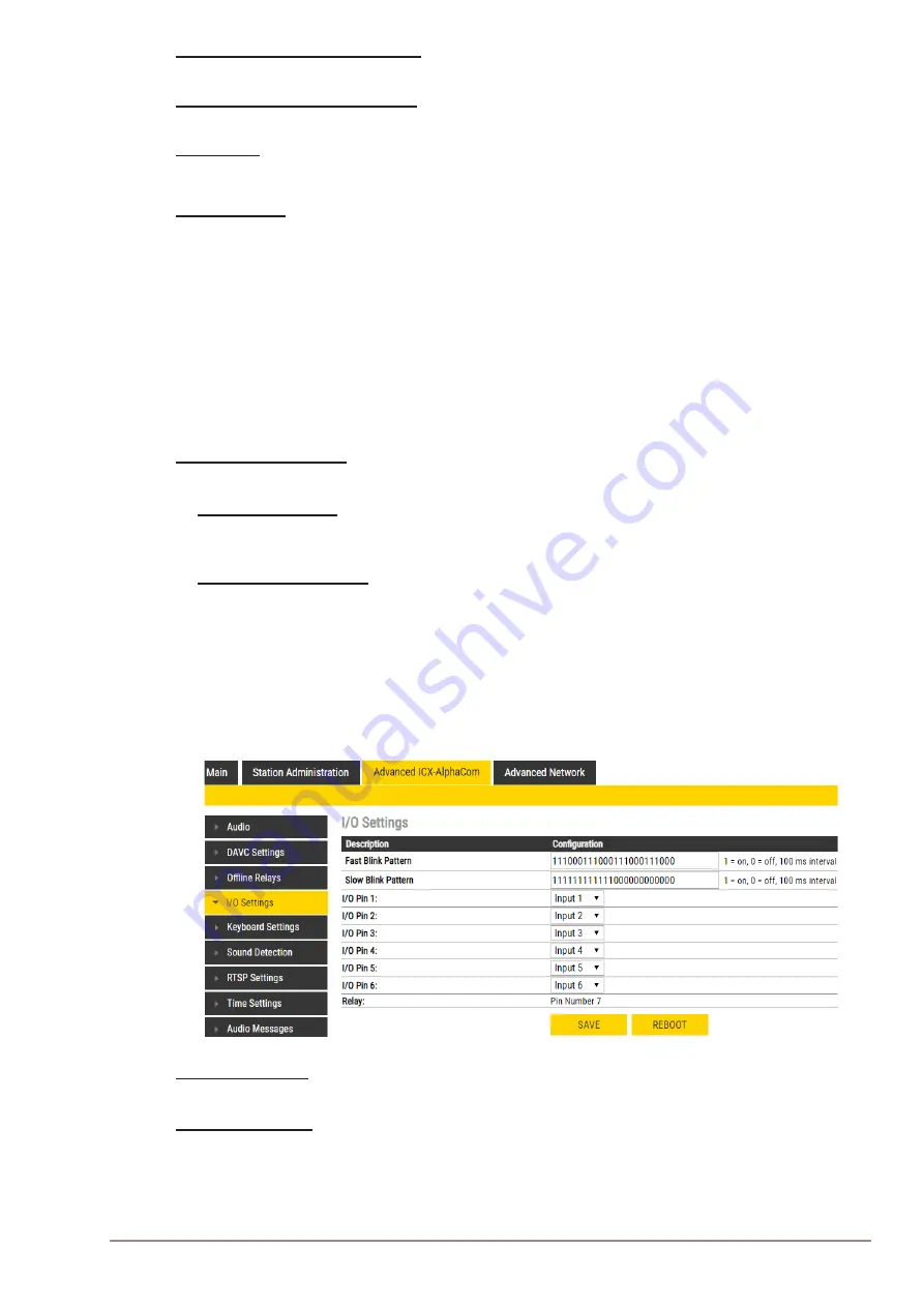
5.4  I/O Settings

The I/Os can either be configured as an Input or as an Output. By default all I/Os are set as Inputs.


● Select 

Advanced ICX-AlphaCom

 > 

I/O Settings 

Fast Blink Pattern


● Set the fast blink pattern for the LEDs

Slow Blink Pattern


● Set the slow blink pattern for the LEDs


● Select either 

Input

 or 

Output

 options from the drop-down box for 

I/O Pins


1

 to 

6

Summary of Contents for ECPIR-3P

Page 1: ...TECHNICAL MANUAL Turbine IP Intercoms TCIS TCIV TFIE TFIX TMIS ECPIR 3P A100K11194 PRE 14 0029...

Page 2: ...1008111010 TA 1 Surface Mount Back Box 1008140010 TA 2 Flush Mount 2 Gang Double Depth Back Box 1008140020 TA 5 Flush Mount Bracket 1008140050 MRBD Multi Relay Board 1009970200 TCIS 2 Turbine Compact...

Page 3: ...ms 19 3 3 2 Connecting TAX 2b Plugbox to TFIX x Ex Intercoms 20 3 4 EMMAI 2H EMMAX 1H Handheld Compact Microphone for Turbine Extended 20 3 4 1 Connecting EMMAI 2H Microphone to TFIE x Industrial Inte...

Page 4: ...61 7 8 Audio Messages 61 7 9 Advanced Configuration Mode 62 7 10 I O Settings 64 8 Common Advanced Network Settings 65 8 1 SNMP Settings 65 8 2 Network Access Control 67 8 3 Firewall Settings 69 9 St...

Page 5: ...utton TCIS 3 TCIV 3 Thermoplastic Frontplate with Single Call Button TCIS 4 Thermoplastic Frontplate with Single Call Button and PMOLED Display TCIS 5 TCIV 5 Thermoplastic Frontplate with Two Call But...

Page 6: ...CIS 1 Station Keys Functions Figure 2 Turbine TCIS 6 Station Keys Functions 1 1 1 TKIS 2 Turbine Kit VoIP Intercom Module Speaker Cancel Microphone Manual Speech Direction Control Call Button Speaker...

Page 7: ...ll Keypad TFIE 2 Industrial Intercom with 6 Programmable Keys TFIE 6 Industrial Intercom with Scrolling Unit PMOLED Display TFIX 1 Ex Intercom with Full Keypad TFIX 2 Ex Intercom with 6 Programmable K...

Page 8: ...8 A100K11194 Turbine Station Configuration Guide Fault LED Call LED Power LED Figure 3 Turbine TFIE 1 TFIX 1 TFIX 4 Station Keys Functions...

Page 9: ...9 Turbine Station Configuration Guide A100K11194 Fault LED Call LED Power LED Figure 4 Turbine TFIE 2 TFIX 2 Station Keys Functions...

Page 10: ...tion Guide Dialing Keys Manual Speech Direction Control Speaker Cancel Private Open Direct Access Keys Fault LED Call LED Power LED Microphone PMOLED Display Scroll Up Scroll Down Confirm Menu Figure...

Page 11: ...11 Turbine Station Configuration Guide A100K11194 Figure 6 TFIX 3 Station Keys Functions Fault LED Call LED Power LED...

Page 12: ...3P is an Indoor Intercom with 3 programmable keys Speaker PTT Key Volume Control Dimmer Fault LED Call LED Power LED Figure 7 ECPIR 3P Intercom Keys Functions 1 2 3 TKIE 2 Turbine Extended Kit The TK...

Page 13: ...itching power COM NO NC contacts are provided Max 250VAC 220VDC 2A 60W Input Output 6 general purpose I Os are available Each I O can be configured as either button input or LED driver Audio Line Out...

Page 14: ...for further information Figure 10 Connectors on Turbine Industrial Station L All connections are made on the main board inside the enclosure of the Turbine Industrial station 2 2 1 Power Supply The T...

Page 15: ...rs for further information 2 3 Connectors on Turbine Ex Figure 11 Connectors on Turbine Ex Station L All connections are made on the main board inside the enclosure of the Turbine Ex station Procedure...

Page 16: ...nclosure 3 1 2 Connection Terminal Block in Industrial Intercoms Accessories are connected to the 9 pin connection terminal block J8 on the main board in the Turbine Industrial enclosure 1 Open the en...

Page 17: ...dio accessory microphone 4 Audio accessory microphone 5 Audio accessory Push To Talk PTT 6 Audio accessory Hook 7 Audio accessory Ground 8 Integrated loudspeaker 9 Integrated loudspeaker Connectors fo...

Page 18: ...ion on 9 Pin Terminal J8 Red PTT PTT Mic Mic LS LS 3 2 2 Connecting TAX 3 Handset to TFIX x Ex Intercoms Connect the wire ferrules on the Handset cable to the terminal block according to the pin confi...

Page 19: ...b Plugbox to TFIE x Industrial Intercoms Plug the IDC connectors on the Plugbox cable into the J8 terminal block according to the pin configuration below 1 6 5 4 3 2 9 8 7 Yellow Green Pink White Blac...

Page 20: ...crophone for Turbine Extended The Compact Microphone comes with a Push To Talk PTT button and 3 meter long cable EMMAI 2H used with Turbine Industrial intercoms EMMAX 1H used with Turbine Ex intercoms...

Page 21: ...tes through its master the ECPIR 3P L Up to four EBMDR 8 modules may be daisy chained to one ECPIR 3P 3 5 1 Connecting EBMDR 8 Expansion Module to ECPIR 3P Intercom 1 Using the small connection cable...

Page 22: ...22 A100K11194 Turbine Station Configuration Guide 3 6 Turbine Relay Module TA 10...

Page 23: ...ddress of the station is automatically obtained in one of two ways 1 An IP address is obtained from a DHCP server if there is one 2 If there is no DHCP server an IP address in the range 169 254 x x wi...

Page 24: ...The following sections describe configuration procedures using the web interface of the station 5 1 Logging into the Station Ensure that the IP address of your PC is in the same range as that of the s...

Page 25: ...e ICX AlphaCom radio button Product Model and Accessory The options presented will depend on the Turbine model Compact Industrial Ex Select one of the options from the Model drop down box Model for Co...

Page 26: ...all receive IP Settings from a DHCP server Static IP Select this option if the IP station shall use a static IP address Enter values for IP address Subnet mask Gateway DNS Server 1 option for network...

Page 27: ...l a setting in the 1 to 3 range will reduce the chance of acoustic feed back howling Digital Analog Mic Switch Switches from Digital to Analog Mic based on settings Options Always Digital Default Alwa...

Page 28: ...ed 0 3 selects different attack release times Lesser values mean faster attack and slower release time AGC Volume 0 7 corresponds to 20 0 dBm Audio Out Source Main audio out speaker sources Voice Audi...

Page 29: ...Time for successive frames after AVC lock due to far end active or optional high near end signal before commencing AVC adjustments A negative sign locks AVC if signal is above upper threshold Valid ra...

Page 30: ...he display may be changed The default text is Scroll to Select Font Size The font size can be either 12 or 16 OLED Brightness Select Brightness levels Extra Dim Dim Default Bright Extra Bright Max Bri...

Page 31: ...dded 5 6 OLED Labels L Note that only Turbine Compact stations configured with OLED Labels TCIS 4 TCIS 5 under Main Settings will have this menu option Select Advanced ICX AlphaCom OLED Labels OLED Di...

Page 32: ...enu Sound Detection Settings Here you can set the minimum amplitude and duration of the audio the DAK to activate etc 5 8 Time Settings Select Advanced ICX AlphaCom Time Settings from the menu Time Se...

Page 33: ...IP Address 10 9 8 7 Turbine IP Station Edge Controller Directory Number 13 Name Reception IP Address 10 9 8 134 LAN Figure 15 IC EDGE System 6 1 Logging into the Station Ensure that the IP address of...

Page 34: ...s described in the following sections Product Model and Accessory The options presented will depend on the Turbine model Compact Industrial or Ex Select one of the options from the Model drop down box...

Page 35: ...ller for them to be auto discovered by the Edge Controller Stations on a different subnet have to be manually added under Manually Added Devices Wait for the stations to boot up approximately 60 secon...

Page 36: ...dspeaker volume during volume override Volume Override is used by Group Calls with Emergency priority ANC Active Noise Cancellation When enabled most of the background noise will be filtered out of th...

Page 37: ...dispatch the checked group calls Busy override allowed When calling a busy station stations with this profile can force a connection by pressing 5 6 8 Group Call The IC EDGE system supports 4 Group C...

Page 38: ...the group call is activated Can be any text Number The number to dial to activate the group call If changed a reboot of the Edge Controller is required for the changes to take effect Answer Group Cal...

Page 39: ...enitel Mobile App is a mobile application for Android and IOS devices The Mobile App enables the use of a mobile device as an intercom station in the IC EDGE system 6 9 1 Add the Mobile App to the Edg...

Page 40: ...A global list of addresses can be created in the address book of the MobileApp Select Edge Controller System Configuration Mobile App To autogenerate a global address list comprising all registered de...

Page 41: ...n Mobile App Under Action Buttons Select the Function for each action button from the dropdown list Enter the Number and Display Name for each button Click SAVE There are 6 functions for the action bu...

Page 42: ...nstalled To install a license Select Edge Controller Licensing Enter the license key in the New License field and click ACTIVATE LICENSE The Licensing table should now show all the licenses that are a...

Page 43: ...Edge Controller 6 10 4 Verify Operation On the Edge Controller device Select Edge Controller System Overview Check that the SIP Device has gotten the Status Registered Verify that you can call to and...

Page 44: ...44 A100K11194 Turbine Station Configuration Guide Check the Configuration box Click SAVE Click RELOAD A new tab called Edge Configuration will now appear...

Page 45: ...he call is routed via the Ringlist Forward Call Forward calls to the configured destination Forwarding will be toggled On Off every time the DAK key is pressed Forwarding status is shown on DAK keys L...

Page 46: ...ng on the current state Incoming Call Accept call Established call Put call on hold disable audio On hold Resumes a call enable audio Send DTMF Sends configured DTMF for key press and key release Send...

Page 47: ...n unattended call can be forwarded to another station after a preset time The call forwarding can include several stations In the example when the call button is pressed the call goes to station numbe...

Page 48: ...call can be go through a call loop a preset number of times In the example when the call button is pressed the call goes to station number 10 If not answered within 12 seconds the call will be forwar...

Page 49: ...follows By checking the With Previous box in the Ringlist one can call several stations in parallel When one of the stations answers it will stop ringing in the other s In the example when the call bu...

Page 50: ...in Edge mode 6 13 1 Script Upload Select Edge Configuration Script Upload Upload Script Click Choose File to select the desired script Click UPLOAD to upload the desired script 6 13 2 Script Configur...

Page 51: ...ed by various events occurring on the station The audio message playback can be triggered by 3 main events DTMF Call Relay There are two ways of configuring audio messages 1 Via the Edge Controller wh...

Page 52: ...events are supported Call Ringing Incoming Outgoing call on the station no auto answer Call Queued Outgoing call from the station has been queued on the master station Call Accepted Incoming Outgoing...

Page 53: ...c The audio message is always routed to the loudspeaker of the station but there is an option to send the audio message as a Microphone signal as well This means that the audio message can be transmit...

Page 54: ...1 Logging into the Station Ensure that the IP address of your PC is in the same range as that of the station IP address Access the station by logging into the web interface using a standard web brows...

Page 55: ...l or Ex Select one of the options from the Model drop down box Model for Compact Kit TKIS 2 Normal TCIS 1 TCIS 2 TCIS 3 OLED Labels TCIS 4 TCIS 5 Scrolling Station TCIS 6 Mini TMIS 1 TMIS 2 Model for...

Page 56: ...Disable Reset to Factory default settings using frontboard and I O Check the box to disable factory reset using frontboard and I O Read IP Address Read IP Address enables an unregistered station to sp...

Page 57: ...condary domain and the tertiary domain Cisco This is for the Cisco environment only with Publisher Subscriber SRST setup where the station is normally registered to Publisher The Subscriber should be...

Page 58: ...ter entering the desired values click SAVE followed by REBOOT to enable the SIP settings 7 4 Audio Settings Select SIP Configuration Audio Speaker Volume Set speaker volume between 0 and 5 Volume Over...

Page 59: ...ons Select SIP Configuration Direct Access Keys L Note that the availability of these parameters and the number of keys depend on the Turbine station type selected under Main Settings For more informa...

Page 60: ...lect the digit DTMF signal that should change the relay to the On Off Slow Flash Fast Flash state Remote Digit For Relay Toggle Select the digit to toggle the relay on off every time the specified DTM...

Page 61: ...relay should change to when the station is off line 7 7 Time Settings Select SIP Configuration Time Time Settings You can enable NTP Network Time Protocol select the time zone and enter the date and...

Page 62: ...upload the amount of space left of the maximum of 20 MB is displayed 7 9 Advanced Configuration Mode Settings for I O Scripts etc described in the following sections are only available in the Advance...

Page 63: ...ation Guide A100K11194 Click RELOAD New menu items such as I O Script under SIP Configuration and a new tab called Advanced SIP will now appear For more information on Script settings see wiki zenitel...

Page 64: ...a keyboard matrix and in this way create more DAKs The options are 2 Inputs input 1 2 DAK 1 3 3 Inputs input 1 3 DAK 1 7 4 Inputs input 1 4 DAK 1 15 Fast Blink Pattern Set the fast blink pattern for...

Page 65: ...nced Network settings are available in ICX AlphaCom Edge Controller and SIP mode 8 1 SNMP Settings SNMP Simple Network Management Protocol is a protocol for centralizing the management of devices in I...

Page 66: ...address of the server receiving SNMP informs This is disabled if the field is left empty SNMP Custom Configuration File Upload the custom snmpd conf file that will be used when running SNMP The uploa...

Page 67: ...he station will send an SNMP trap when a sound test is successful Input Button Pressed If enabled the station will send an SNMP trap when an input is activated Input Button Released If enabled the sta...

Page 68: ...client verifies that server certificates presented to the client have the correct signatures have not expired and were issued by a trusted root certification authority CA It s enabled by default Fast...

Page 69: ...le or disable AudioData on station disabled by default TFTP Server Enable or disable TFTP Server on station enabled by default SNMP Enable or disable SNMP on station enabled by default SIP udp Enable...

Page 70: ...ne Ex stations have a built in Flowire component Refer to A100K11958 FCDC3 Flowire Configuration Manual when upgrading software for Ex stations 9 1 Prerequisites The upgrade methods require that an TF...

Page 71: ...The station will now try to contact the TFTP server The upgrade procedure takes about 3 minutes The process can be monitored by clicking the Log viewer tab in the TFTP server program L During an upgra...

Page 72: ...gistered in the AlphaCom server exchange Reason Station has not been programmed in AlphaPro 10 1 2 ECPIR 3P Industrial Ex Stations Power LED Green Steady light Power is OK Fault LED Yellow Steady ligh...

Page 73: ...no 0 count the procedure has failed and you have to start again 4 Press the call key number keys or DAKs to make the station speak its IP address Factory default values Station IP address determined b...

Page 74: ...ernal connections Pin 1 2 24 VDC for external secondary power if PoE is not used Pin 1 is positive Pin 3 COM relay Pin 4 NO relay Pin 5 NC relay P4 Loudspeaker Electret microphone Pin 1 10W Speaker am...

Page 75: ...utton Input or LED Driver Pin 8 Button Input or LED Driver Pin 9 600 ohm balanced line out Pin 10 600 ohm balanced line out A 3 Output Connectors 1 Relay The extra relay for any of the 6 I O pins is c...

Page 76: ...gether with the Multi Relay Board MRBD to provide up to 6 additional relay contacts A 5 PCB Rear J6 10 pin terminal for digital MEMS Microphone Pin 1 Left mic select Vdd Pin 2 Right mic select GND Pin...

Page 77: ...77 Turbine Station Configuration Guide A100K11194 A 6 Front Board Front A 7 Front Board Rear...

Page 78: ...ret microphone Pin 1 10W Speaker amplifier Pin 2 10W Speaker amplifier Pin 3 Electret Microphone Pin 4 Electret Microphone B 2 Input Connectors P4 10 pin plug on terminal for external connections Pin...

Page 79: ...79 Turbine Station Configuration Guide A100K11194...

Page 80: ...in whole must include this legend Zenitel All rights reserved customer service zenitel com www zenitel com A100K11194 The WEEE Directive does not legislate that Zenitel as a producer shall collect end...

Reviews: