background image

RA_6360_6375_01 - EN 

- Console -

- Install right lower handlebar

(see section 02.10.04)

- Install strut

(see section 08.01.02)

- Install left / right cover

(see section 08.02.02)

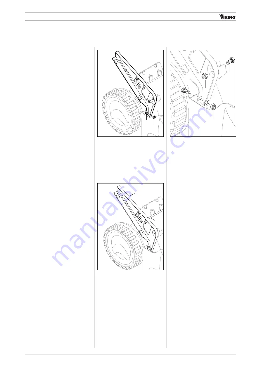
08.03.04 Installing right console

• Insert bolts 

1

and tighten nuts 

3

with

washer 

2

(12-18 Nm).

2

3

3

1

1

• Push rod 

1

through bore 

A

of

console 

2

.

2

1

A

08.03.03 Removing right

console

- Remove right lower handlebar

(see section 02.10.03)

- Remove strut

(see section 08.01.01)

- Remove left / right cover

(see section 08.02.01)

• Remove nuts 

1

, washer 

2

and

bolts

3

.

• Remove right console 

4

.

2 1

3

1

3

4

- Install left lower handlebar

(see section 02.10.02)

- Install strut

(see section 08.01.02)

- Install left / right cover

(see section 08.02.02)

- Install detent segment

(see section 07.04.04)

81

Summary of Contents for MB 650

Page 1: ...EN Repair instructions 2008 05 www viking garden com MB 650 MB 655 ...

Page 2: ... required for the completion of this section see pt 3 General For easier use and better understanding of these repair instructions graphic symbols with the following meanings are used in the text and illustrations In the text operation to be performed which corresponds to the illustration above the text field operation to be performed but which is not shown in the illustration above the text field...

Page 3: ...ar height adjustment 21 02 11 02 Installing handlebar height adjustment 21 02 12 Replacing charging socket 22 02 12 01 Removing charging socket 22 02 12 02 Installing charging socket 22 02 13 Replacing ignition lock 23 02 13 01 Removing ignition lock 23 02 13 02 Installing ignition lock 23 03 Control bars and levers 24 03 01 Replacing wheel drive control bar 24 03 01 01 Removing wheel drive contro...

Page 4: ...ght glass 61 05 08 01 Removing sight glass 61 05 08 02 Installing sight glass 62 05 09 Replacing V belt cover 62 05 09 01 Removing V belt cover 62 05 09 02 Installing V belt cover 62 05 10 Replacing left right protection bumpers 63 05 10 01 Removing left right protection bumpers 63 05 10 02 Installing left right protection bumpers 63 05 11 Replacing guiding plate 63 05 11 01 Removing guiding plate...

Page 5: ... 06 Replacing blade mounting ball bearing 89 11 06 01 Removing blade mounting ball bearing 89 11 06 02 Installing blade mounting ball bearing 90 11 07 Replacing clutch drum 90 11 07 01 Removing clutch drum 90 11 07 02 Installing clutch drum 91 11 08 Replacing brake band lever 92 11 08 01 Removing brake band lever 92 11 08 02 Installing brake band lever 93 11 09 Replacing brake band 94 11 09 01 Rem...

Page 6: ...onnecting wiring harness 112 14 07 Cable wiring harness guide 112 14 07 01 MB 650 0 T 113 14 07 02 MB 650 0 V VM MB 655 0 V VM 113 14 07 03 MB 650 0 VS 114 14 07 04 MB 650 0 VE 114 14 07 05 MB 655 0 G GM 115 14 07 06 MB 655 0 GS 115 14 07 07 MB 650 0 VQ 116 14 07 08 MB 655 0 GQ 116 14 07 09 MB 650 0 TK 117 14 07 10 MB 650 0 KS 117 14 07 11 MB 655 0 KS 118 14 07 12 MB 655 0 GK 118 14 07 13 MB 650 0...

Page 7: ...the repair work is being carried out Distribution to third parties is prohibited Only use high quality tools accessories and spare parts Otherwise there may be a risk of accidents resulting in personal injury or damage to the appliance VIKING recommends the use of original VIKING tools accessories and spare parts Their properties are optimally adapted to the appliance and the user s requirements W...

Page 8: ...le guide s 1 into housing 2 and clip onto handlebar 02 Handlebar 1 2 2 1 2 1 Remove cap nuts 1 and remove washers 2 Pull out bolts 3 from handlebar and remove strut 4 1 2 3 4 3 2 1 Fit strut 1 and insert bolts 2 through handlebar Install cap nuts 4 with washers 3 and tighten 8 10 Nm 4 3 2 1 2 3 4 02 03 01 Removing inside right housing half Remove right left cable guide see section 02 01 01 Push wh...

Page 9: ...moving inside left housing half Remove right left cable guide see section 02 01 01 Remove reinforcement strut see section 02 02 01 Push wheel drive control bar 1 to the left and detach from inside right housing half 2 Pull wheel drive control bar 1 upwards and rest on right housing halves 1 2 2 1 Remove screws 1 2 1 2 1 1 Lift inside left housing half 1 slightly and push wheel drive lever 2 forwar...

Page 10: ...housing half 1 together with wheel drive control bar 2 1 2 Remove screw 1 1 Models without blade clutch without Quick Start Remove cable support 1 1 Remove outside left housing half 1 1 02 03 04 Removing outside left housing half Remove inside left housing half see section 02 03 03 ...

Page 11: ... Nm 1 3 2 2 2 02 04 01 Attaching outside right housing half Fit housing half 1 and tighten screw 2 1 2 Nm 1 2 02 04 03 Attaching outside left housing half Fit outside left housing half 1 onto handlebar and tighten screw 2 1 2 Nm 1 2 Models without blade clutch without Quick Start Insert cable support and attach motorstop cable 2 1 Models with blade clutch with Quick Start Attach blade clutch cable...

Page 12: ...n the right 2 2 A 1 Install right left cable guide see section 02 01 02 Models without blade clutch without Quick Start Remove bracket see section 03 08 01 Models with blade clutch Remove throttle lever see section 03 09 01 MB 650 0TK MB 655 0 GK Remove throttle lever see section 03 09 01 MB 650 0T Remove inside right housing half see section 02 03 01 MB 650 0T Attach inside right housing half see...

Page 13: ... half see section 02 03 04 Attach outside left housing half see section 02 04 04 02 05 06 Assembling outside left housing half Insert wheel drive cable adjusting element 1 Tighten screw 2 1 2 Nm 02 05 04 Assembling inside left housing half Attach inside left housing half see section 02 04 03 MB 650 0VE Install ignition lock see section 02 13 02 MB 650 0VE Install charging socket see section 02 12 ...

Page 14: ...02 07 01 Removing cable anti kink protection Detach cables 1 1 Remove rotary handles 1 Remove cable anti kink protection 2 bolt 3 from centre handlebar section Note Only one cable anti kink protection 2 is required on the MB 650 0T A bolt 3 is installed in place of the second cable guide 1 1 2 2 3 02 06 02 Attaching upper handlebar Attach outside right housing half see section 02 04 01 Attach hand...

Page 15: ... position of cable anti kink protection see Fig Tighten rotary handles 2 Attach cables 1 ensure correct installation position of cables see Fig 02 08 Replacing starter cable guide 02 08 01 Removing starter cable guide Detach starter cable Remove screw 1 Remove starter cable guide 2 1 2 02 08 02 Installing starter cable guide Attach starter cable guide 1 to handlebar Tighten screw 2 5 7 Nm Insert s...

Page 16: ... section 1 Remove left centre handlebar section 1 1 Tighten nut 1 8 10 Nm 1 Attach motorstop control bar 1 blade stop control bar 1 on left in bore A on centre handlebar section 1 A 1 1 Remove nut 1 Attach left centre handlebar section 1 Remove outside left housing half see section 02 03 04 Remove cable anti kink protection see section 02 07 01 Install cable anti kink protection see section 02 07 ...

Page 17: ...utch Quick Start lever see section 03 04 01 1 Remove nut 1 1 Remove right centre handlebar section 1 1 Remove outside right housing half see section 02 03 02 Remove starter cable guide see section 02 08 01 Remove cable anti kink protection see section 02 07 01 Install cable anti kink protection see section 02 07 02 02 09 04 Installing right centre handlebar section Attach right centre handlebar se...

Page 18: ...ection 02 08 02 Attach outside right housing half see section 02 04 01 02 10 Replacing lower handlebar 02 10 01 Removing left lower handlebar Remove handlebar 1 1 1 2 3 Remove nut 1 Remove collared washer 2 and spring washer 3 2 1 Pull out bolt 1 and remove left lower handlebar 2 Remove cable anti kink protection see section 02 07 01 Remove housing cover assembly see section 05 02 01 02 10 02 Inst...

Page 19: ...handlebar Remove handlebar 1 1 Remove cable anti kink protection see section 02 07 01 Remove housing cover assembly see section 05 02 01 2 1 Remove cap nut 1 and remove washer 2 1 2 3 Remove nut 1 Remove collared washer 2 and spring washer 3 Fit spring washer and collared washer onto bolt Note Ensure correct installation position of spring washer 1 see Fig 1 2 1 2 Tighten nut 1 12 18 Nm 1 ...

Page 20: ... kink protection see section 02 07 02 2 1 Pull out bolt 1 and remove right lower handlebar 2 02 10 04 Installing right lower handlebar Fit left lower handlebar 1 and insert bolt 2 2 1 Fit spring washer and collared washer onto bolt Note Ensure correct installation position of spring washer 1 see Fig 2 1 1 2 Attach housing cover assembly see section 05 02 04 ...

Page 21: ...ach housing cover assembly see section 05 02 04 2 1 Remove cap nut 1 and remove washer 2 1 1 2 2 1 Pull height adjustment rod 1 to the left and remove from console 2 on the right hand side Pull out height adjustment rod 1 to the right 1 1 2 1 2 Insert height adjustment rod 1 from inside into console 2 on left Insert height adjustment rod 1 in console 2 on right Fit washer 1 onto rod 2 and tighten ...

Page 22: ...e left housing half see section 02 04 03 Disconnect battery see section 13 01 01 Connect battery see section 13 02 02 1 Remove nut 1 and remove charging socket from housing half 1 2 Remove sealing ring 1 from charging socket 2 2 1 2 1 Attach connection cables 1 red 2 black polarity is indifferent 1 2 3 Fit sealing ring 1 onto charging socket 2 Insert charging socket 2 from outside through opening ...

Page 23: ... with toothed disk 2 from inside through opening in housing half Tighten nut 3 with convex side facing outwards hand tight 1 2 Nm Attach inside left housing half see section 02 04 03 Connect battery see section 13 01 02 1 2 1 2 Attach connection cables 1 2 polarity is indifferent 02 13 Replacing ignition lock 02 13 01 Removing ignition lock Disconnect battery see section 13 01 01 Remove inside lef...

Page 24: ... 02 01 Removing motorstop control bar Remove inside right housing half see section 02 03 01 Remove cable support 1 Remove inside left housing half see section 02 03 03 03 01 02 Installing wheel drive control bar Attach inside left housing half see section 02 04 04 03 Control bars and levers 1 Detach motorstop cable 1 from control bar 2 1 2 Press motorstop control bar 1 together at both sides and d...

Page 25: ...3 1 A 1 A 1 Attach motorstop cable 1 to control bar 2 1 2 Fit motorstop cable 1 in cable support 2 and insert cable support into outside left housing half 2 1 03 03 Replacing blade stop Quick Start control bar 03 03 01 Removing blade stop Quick Start control bar Remove inside right housing half see section 02 03 01 Press motorstop Quick Start control bar 1 together at both sides and detach from ha...

Page 26: ... Attach inside right housing half see section 02 04 02 Remove locking lever 1 from control bar 2 1 2 03 03 02 Installing blade stop Quick Start control bar Fit detent lever 1 onto control bar 2 1 2 Press control bar 1 together and insert in guides A Engage locking lever 1 in detent lever 2 1 A 1 A 1 ...

Page 27: ...02 03 02 1 Remove nut 1 and pull out bolt 2 Remove blade clutch Quick Start lever 3 with washer 4 and bushing 5 1 4 2 3 5 03 04 02 Dismantling blade clutch Quick Start lever Detach cable 1 from blade clutch Quick Start lever 2 1 2 Detach detent lever 1 from blade clutch Quick Start lever 2 Remove 1 screw remove reinforcement 2 Detach detent lever 3 from blade clutch Quick Start lever 4 1 2 from se...

Page 28: ... 1 onto blade clutch Quick Start lever 2 ensure correct installation position see Fig 1 2 Attach cable 1 to blade clutch Quick Start lever 2 1 2 03 04 04 Installing blade clutch Quick Start lever Push bushing 1 into blade clutch Quick Start lever 2 and attach to handlebar 1 2 Insert bolt 1 from outside through handlebar Fit washer 2 and tighten nut 3 1 2 Nm 3 2 1 03 04 03 A 03 04 03 A 03 04 03 A f...

Page 29: ...tent lever 03 05 01 Removing detent lever Dismantle blade clutch Quick Start lever see section 03 04 02 Remove blade clutch Quick Start lever see section 03 04 01 03 05 02 Installing detent lever Assemble blade clutch Quick Start lever see section 03 04 03 Install blade clutch Quick Start lever see section 03 04 04 Attach outside right housing half see section 02 04 01 1 1 A Insert motorstop Quick...

Page 30: ...nsert motorstop Quick Start control bar 1 into guide A on handlebar on right Engage locking lever 1 in detent lever 2 03 07 ReplacingVario three speed lever 03 07 01 RemovingVario three speed lever Detach handle 1 from lever 2 Remove inside right housing half see section 02 03 01 1 2 Detach cable 1 from bracket 1 Illustrations show version with blade clutch additional throttle lever ...

Page 31: ... 07 02 InstallingVario three speed lever Remove lever 1 from housing half the spring washers must not be removed 1 Check correct position of spring washers 1 opposing position 1 1 Illustrations show version with blade clutch additional throttle lever Detach cable 1 from lever 2 1 2 2 1 Remove screw 1 with washer 2 1 2 ...

Page 32: ...ttach cable 1 to lever 2 large bore on left see Fig 1 2 2 1 Attach inside right housing half see section 02 04 02 03 08 Replacing bracket 03 08 01 Removing bracket Remove spring washers 1 2x Remove Vario three speed lever see section 03 07 01 03 07 01 1 1 Unclip bracket 1 from housing half 1 ...

Page 33: ... 0TK Remove inside right housing half see section 02 03 01 Models withVario three speed gearbox Remove spring washers 1 2x Models withVario three speed gearbox Remove Vario three speed lever see section 03 07 01 1 1 03 08 02 Installing bracket Clip bracket 1 into housing half Install Vario three speed lever see section 03 07 02 1 Insert spring washers 1 2x ensure opposing position 1 1 1 1 ...

Page 34: ...housing half see section 02 04 02 1 A 2 Insert throttle lever 1 into housing half and clip in place 1 Fit handle 1 1 Detach cable 1 from bracket 2 and from bore A on throttle lever 1 A 2 Models withVario three speed gearbox Insert spring washers 1 2x ensure opposing position 1 1 1 1 Models withVario three speed gearbox Install Vario three speed lever see section 03 07 02 ...

Page 35: ...etaining ring 1 using long nose pliers 1 Detach translatory lever 1 from axle 2 swivel plate 1 2 Remove screws 1 1 1 1 1 Axle with carrying handle 1 1 Remove nut 1 remove translatory lever 2 from axle 3 swivel plate with pin 1 3 2 Models MB 650 0 from serial number 4 31 244 752 Models MB 655 0 from serial number 4 31 230 688 Models MB 655 1 Models MB 650 0 up to serial number 4 31 244 751 Models M...

Page 36: ...lever Remove screw 1 1 Remove bottom part 1 and upper part 2 of carrying handle from axle 3 1 3 2 04 01 03 Assembling front axle 04 01 04 Installing front axle Fit bottom part 1 and upper part 2 of carrying handle onto axle 3 1 3 2 Tighten screw 1 1 2 Nm 1 Insert axle 1 1 Tighten screws 1 5 7 Nm 1 1 1 1 Note Set the cutting height adjustment to the highest position position 7 ...

Page 37: ...emove height adjustment spring see section 07 01 01 Remove retaining ring 1 using long nose pliers 1 Models MB 650 0 up to serial number 4 31 244 751 Models MB 655 0 up to serial number 4 31 230 687 Attach translatory lever 1 to axle 2 swivel plate 1 2 04 01 04 A Fit washer 1 to pin of axle 2 Attach translatory lever 3 in direction of arrow Tighten nut 4 4 6 Nm 1 3 2 4 Models MB 650 0 from serial ...

Page 38: ...rbox support see section 06 04 03 Detach V belt at gearbox Models with three speed gearbox Remove cable support see section 06 06 01 Models with single speed gearbox Detach wheel drive cable 1 at gearbox 2 Models withVario gearbox Detach wheel drive cable 1 and speed control cable 2 at gearbox 3 tip gearbox backwards for this purpose Models with three speed gearbox Detach three speed cable 1 from ...

Page 39: ...x 1 to the left in direction of arrow Remove freewheel wedge 2 Remove freewheel wedge 1 on right side of shaft 2 through bore A Chassis Remove retaining ring 1 left right Remove washer 2 and pinion 3 from shaft 4 left right Remove axle 1 with gearbox from housing 04 02 02 Dismantling rear axle ...

Page 40: ...ring 1 and washer 2 from bushing right side Remove gearbox 1 from axle 2 in direction of arrow Insert washer 1 and bearing 2 into axle bushing 3 left side Remove bearing 1 and washer 2 from axle bushing left side 04 02 03 Assembling rear axle ...

Page 41: ...RA_6360_6375_01 EN 41 Insert washer 1 and bearing 2 into axle bushing 3 right side Fit shim ring 1 onto shaft 2 left side Chassis Insert gearbox 1 into axle 2 in direction of arrow ...

Page 42: ...edge 1 left side and push gearbox 2 to the right up to stop Note Ensure correct installation position of freewheel wedge 1 see Fig Fit pinion 1 Part No 6105 704 7410 Fit washer 2 Fir retaining ring 3 on axle 4 Fit shim ring 1 onto shaft 2 right side ...

Page 43: ...x Insert axle 1 with gearbox into housing Chassis Note Ensure correct installation position of freewheel wedge 1 see Fig Insert freewheel wedge 1 into shaft 2 through bore A right side Fit pinion 1 Part No 6105 704 7400 Fit washer 2 Fir retaining ring 3 on shaft 4 ...

Page 44: ...at gearbox 2 Models withVario gearbox Attach wheel drive cable 1 and speed control cable 2 at gearbox 3 tip gearbox backwards for this purpose Models with three speed gearbox Attach three speed cable 1 at gearbox 2 Models with three speed gearbox Install cable support see section 06 06 02 Do not attach housing cover assembly ...

Page 45: ... gearbox Attach translatory lever 1 to axle 2 swivel plate 1 2 Fit retaining washer 1 to pin and clip in using long nose pliers 1 Install rear wheel cover see section 04 06 02 Install height adjustment spring see section 07 01 02 Models with single speed Vario gearbox Install single speed Vario gearbox support see section 06 04 02 Models with three speed gearbox Install three speed gearbox support...

Page 46: ...1 firmly onto wheel 4 1 4 2 3 3 04 03 04 Installing rear wheel cap Position wheel cap 1 and push under rubber lip of tyre 1 04 04 Replacing wheel Remove bolt 1 04 04 01 Removing front wheel 1 Remove clamping ring 1 1 Remove front wheel cap see section 04 03 01 Detach clamping ring from wheel hub by striking it lightly rubber mallet up to serial number 4 31 427 503 04 04 01 A ...

Page 47: ...rear wheel cap see section 04 03 02 Remove bolt 1 1 Detach clamping ring from wheel hub by striking lightly rubber mallet Remove clamping ring 1 1 Remove wheel 1 1 up to serial number 4 31 427 503 from serial number 4 31 427 504 from serial number 4 31 427 504 04 04 01 A 04 04 01 A 04 04 02 A 04 04 02 A 04 04 02 A ...

Page 48: ...l 1 onto axle 04 04 03 Installing front wheel 1 Fit clamping ring 1 and tighten bolt 2 10 Nm 1 2 Tighten nut 1 10 Nm 1 Install front wheel cap see section 04 03 03 Chassis 48 up to serial number 4 31 427 503 up to serial number 4 31 427 503 from serial number 4 31 427 504 04 04 03 A 04 04 03 A 04 04 03 A 04 04 04 A ...

Page 49: ...5 01 Removing wheel bearing 2 1 2 2 1 2 1 Drive wheel bearings 1 2 out from inside using a punch Remove spacer sleeve 3 2 1 3 2 1 3 2 1 2 Remove front wheel see section 04 04 01 Remove rear wheel see section 04 04 02 Tighten nut 1 6 10 Nm 1 49 up to serial number 4 31 427 503 from serial number 4 31 427 504 from serial number 4 31 427 504 04 04 04 A 04 04 04 A ...

Page 50: ... Installing wheel bearing Install front wheel see section 04 04 03 Install rear wheel see section 04 04 04 Warning Ensure straight installation position of wheel bearings Install spacer sleeve 1 Press in wheel bearings 2 3 3 2 1 3 2 1 Warning Ensure straight installation position of wheel bearings up to serial number 4 31 427 503 up to serial number 4 31 427 503 from serial number 4 31 427 504 04 ...

Page 51: ...4 06 01 04 07 02 Removing left drive pinion Remove rear wheel cover see section 04 06 01 Remove cover 1 1 Fit cover 1 onto axle Fit washer 2 1 2 Fit cover 1 onto axle 1 04 06 02 Installing rear wheel cover Install rear wheel see section 04 04 04 51 up to serial number 4 31 427 503 from serial number 4 31 427 504 from serial number 4 31 427 504 04 06 02 A 04 06 02 A 04 06 02 A ...

Page 52: ...07 01 Fit pinion 1 Part No 6105 704 7410 fit washer 2 and install retaining ring 3 04 07 04 Installing left drive pinion Install rear wheel cover see section 04 06 02 Fit pinion 1 Part No 6105 704 7400 fit washer 2 and install retaining ring 3 04 07 03 Installing right drive pinion Install rear wheel cover see section 04 06 02 Remove retaining ring 1 washer 2 and pinion 3 ...

Page 53: ... speed Vario gearbox Removing single speed Vario gearbox support see section 06 04 01 Models with three speed gearbox Remove three speed gearbox support see section 06 04 03 Remove shim ring 1 Push gearbox 1 in direction of arrow to left and remove freewheel wedge 2 Insert freewheel wedge 1 through bore A 04 08 03 Installing right freewheel wedge Note Ensure correct installation position of freewh...

Page 54: ...drive shaft bearing Install rear axle with gearbox see section 04 02 04 Assemble rear axle see section 04 02 03 Fit shim ring 1 Install left drive pinion see section 04 07 04 Install right freewheel wedge see section 04 08 03 Models with single speed Vario gearbox Install single speed Vario gearbox support see section 06 04 02 Models with three speed gearbox Install three speed gearbox support see...

Page 55: ...t console see section 08 03 01 Remove right console see section 08 03 03 Remove guiding plate see section 05 11 01 Remove right left protection bumpers see section 05 10 01 05 01 02 Installing housing Install guiding plate see section 05 11 02 Install right left protection bumpers see section 05 10 02 Install right console see section 08 03 04 Install left console see section 08 03 02 Install rear...

Page 56: ...see section 05 05 01 05 02 03 Assembling housing cover assembly Install flap see section 05 05 04 Install spring see section 05 04 02 Install height adjustment handle see section 05 03 02 05 02 04 Attaching housing cover assembly Fit the housing cover 1 1 Note Set the cutting height adjustment to the highest position position 7 Remove screws 1 2 Two screws located under ejection flap 1 1 1 2 1 56 ...

Page 57: ...T V VE VM MB 655 0V VM G GM MB 655 1V VM G Attach motorstop cable 1 at engine 1 1 Remove screw 1 1 Detach 1 handle from housing 1 Tighten screws 1 2 5 6 Nm 1 1 1 2 1 1 05 03 Replacing height adjustment handle 05 03 01 Removing height adjustment handle Remove housing cover assembly see section 05 02 01 57 ...

Page 58: ...used Note For easy installation of the spring the STIHL special service tool 5910 890 2800 can be used 1 2 3 05 04 01 Removing spring Attach housing cover assembly see section 05 02 04 Remove housing cover assembly see section 05 02 01 Attach spring 1 in opening A of the flap 2 and in rib B of the housing 3 1 3 2 1 1 B A 05 04 02 Installing spring Attach housing cover assembly see section 05 02 04...

Page 59: ...sly engage flap 1 in recess C A C 1 B 05 05 01 Removing flap 05 05 04 Installing flap Remove housing cover assembly see section 05 02 01 05 05 02 Dismantling flap Remove handle shell see section 05 06 01 05 05 03 Assembling flap Install handle shell see section 05 06 02 Remove spring see section 05 04 01 Attach housing cover assembly see section 05 02 04 Install spring see section 05 04 02 05 05 R...

Page 60: ... 06 Replacing handle shell 05 07 Replacing translatory lever cover Clip handle shell 1 in flap 2 1 2 05 06 02 Installing handle shell Unclip translatory lever cover 1 from housing on underside of appliance 1 05 07 01 Removing translatory lever cover Remove housing cover assembly see section 05 02 01 60 RA_6360_6375_01 EN ...

Page 61: ...ightly lift translatory lever cover 1 and remove slowly in direction of arrow The height indicator pointer is withdrawn from the sight glass in the process 1 05 08 Replacing sight glass 05 08 01 Removing sight glass Remove translatory lever cover see section 05 07 01 Attach housing cover assembly see section 05 02 04 05 07 02 Dismantling translatory lever cover Remove sight glass see section 05 08...

Page 62: ... cover see section 05 07 04 Fit V belt cover 1 over V belt into the recess in the housing 1 05 09 02 InstallingV belt cover Attach housing cover assembly see section 05 02 04 Remove V belt cover 1 1 05 09 ReplacingV belt cover 05 09 01 RemovingV belt cover Remove housing cover assembly see section 05 02 01 62 RA_6360_6375_01 EN ...

Page 63: ...ght protection bumpers 05 10 01 Removing left right protection bumpers Remove screws 1 1 1 Remove guiding plate 1 1 05 11 Replacing guiding plate 05 11 01 Removing guiding plate Engage protection bumper 1 in guides and tighten screws 2 1 2 Nm 1 2 2 2 05 10 02 Installing left right protection bumpers 63 ...

Page 64: ...te Remove bolts 1 1 1 1 Fit lower cover 1 and tighten screws 2 6 8 Nm 1 2 2 2 Remove lower cover 1 1 05 12 Replacing lower cover 05 12 01 Removing lower cover 05 12 02 Attaching lower cover Remove mowing blade see section 09 01 01 Install mowing blade see section 09 01 02 64 RA_6360_6375_01 EN ...

Page 65: ...rear axle with gearbox see section 04 02 04 06 Gearbox 06 02 ReplacingV belt pulley 06 02 01 Removing single speedV belt pulley Remove V belt cover see section 05 09 01 Drive out roll pin 1 Push screwdriver 1 between V belt 2 and V belt pulley 3 Actuate motorstop control bar 5 in order to release the engine brake Slowly pull out starter cable 4 in order to lift the V belt off the V belt pulley 1 3...

Page 66: ...lt Detach speed control cable 1 from gearbox Drive in roll pin 1 Fit V belt 1 onto V belt pulley 2 Actuate motorstop control bar 4 in order to release the engine brake Slowly pull out starter cable 3 in order to attach the V belt to the V belt pulley 1 2 3 4 06 02 02 Installing single speed V belt pulley Attach V belt pulley 1 to gearbox 2 66 RA_6360_6375_01 EN ...

Page 67: ...ley and adjusting element Fit washer 1 and V belt pulley 2 onto gearbox 3 Drive in roll pin 1 Remove Vario adjusting element 1 from gearbox 2 Fit Vario adjusting element 1 onto gearbox 2 Drive out roll pin 1 Remove V belt pulley 1 with washer 2 from gearbox 3 67 ...

Page 68: ...Insert Vario drive cable 1 in bore A and then attach to support B Push screwdriver 1 between V belt 2 and V belt pulley 3 Models without blade clutch without Quick Start Actuate motorstop control bar 5 in order to release the engine brake Models with Quick Start Actuate motorstop control bar 5 actuate Quick Start lever 6 in order to release the engine brake deactivate Quick Start beforehand see se...

Page 69: ...2 03 Press ball bearing 1 out of Vario adjusting element 2 Install V belt cover see section 05 09 02 Fit V belt 1 onto V belt pulley 2 Models without blade clutch without Quick Start Actuate motorstop control bar 4 in order to release the engine brake Models with Quick Start Actuate motorstop control bar 4 actuate Quick Start lever 5 in order to release the engine brake deactivate Quick Start befo...

Page 70: ...er assembly see section 05 02 04 06 04 Replacing gearbox support Remove screw 1 Slightly raise gearbox support 2 and remove downwards Attach gearbox support 1 from below bore in gearbox support aligns with second lug from right in housing Tighten screw 2 5 6 Nm 06 04 01 Removing single speed Vario gearbox support 06 04 02 Installing single speed Vario gearbox support Remove housing cover assembly ...

Page 71: ...ove housing cover assembly see section 05 02 01 Attach housing cover assembly see section 05 02 04 First attach spring 1 to the lever bore A then to the housing bore B using long nose pliers 06 05 04 Installing three speed gearbox return spring Attach housing cover assembly see section 05 02 04 Detach spring 1 from lug A and detach from lever B 06 05 01 RemovingVario gearbox return spring 06 05 Re...

Page 72: ...w 1 5 6 Nm 06 06 02 Installing cable support Install V belt cover see section 05 09 02 Unclip three speed gearshift cable 1 from cable support 2 Detach wheel drive cable 1 from lever 2 Unclip wheel drive cable 1 from cable support 3 and remove the cable Remove screw 1 06 06 01 Removing cable support 06 06 Replacing cable support Remove V belt cover see section 05 09 01 Detach V belt 72 RA_6360_637...

Page 73: ...1 VIKING special service tool height adjustment 6375 890 8800 Attach spring 1 to housing 3 using VIKING special service tool 2 1 2 3 07 01 02 Installing height adjustment spring Attach housing cover assembly see section 05 02 04 07 Height adjustment Note Two bores are provided on the translatory lever designated K and B On appliances with KAWASAKI engines the spring must be attached at bore K and ...

Page 74: ...retaining ring 1 using long nose pliers 1 07 03 Replacing translatory lever 07 03 01 Removing translatory lever Remove front wheel see section 04 04 01 Remove height adjustment indicator see section 07 05 01 Remove rear wheel cover see section 04 06 01 Remove height adjustment spring see section 07 01 01 Remove detent segment tension spring see section 07 02 01 Insert spring 1 in bore A of console...

Page 75: ...ry lever 2 Detach translatory lever 1 from axle 2 swivel plate 1 2 Slightly raise detent segment 1 and remove translatory lever 2 07 03 02 Installing translatory lever 07 03 01 A 07 03 01 A Unscrew nut 1 detach translatory lever 2 from axle 3 swivel plate with pin 1 3 2 Models MB 650 0 from serial number 4 31 244 752 Models MB 655 0 from serial number 4 31 230 688 Models MB 655 1 07 03 01 A 75 ...

Page 76: ... adjustment indicator see section 07 05 02 Install front wheel see section 04 04 03 Install rear wheel cover see section 04 06 02 1 3 2 4 Models MB 650 0 from serial number 4 31 244 752 Models MB 655 0 from serial number 4 31 230 688 Models MB 650 0 up to serial number 4 31 244 751 Models MB 655 0 up to serial number 4 31 230 687 07 03 02 A 07 03 02 A Fit washer 1 to pin of axle 2 Attach translato...

Page 77: ...individual spare part 07 04 03 Assembling detent segment from serial number 4 30 856 348 up to serial number 4 30 856 347 up to serial number 4 30 856 347 Remove nut 1 1 Remove detent segment 2 with bolt 1 1 2 07 04 Replacing detent segment 07 04 01 Removing detent segment Remove detent segment tension spring see section 07 02 01 Tighten screws 1 2 tighten nuts 3 1 Nm bushing 4 and sheet metal rei...

Page 78: ...e height adjustment indicator 1 1 07 05 02 Installing height adjustment indicator Install translatory lever cover see section 05 07 04 Attach height adjustment indicator 1 1 Tighten nut 1 4 6 Nm 1 Fit detent segment 1 and insert bolt 2 in bore A 1 A 2 Install detent segment tension spring see section 07 02 02 07 04 04 Installing detent segment 78 RA_6360_6375_01 EN ...

Page 79: ... 08 02 01 Removing left right cover Remove housing cover assembly see section 05 02 01 Attach housing cover assembly see section 05 02 04 08 Console Remove nuts 1 and remove bolts 2 Remove screws 3 Detach strut 1 from console left right 08 01 02 Installing strut Push the handlebar apart slightly and hold Insert strut 1 in console left right Tighten screws 2 12 18 Nm Unclip cover 1 from console 3 u...

Page 80: ...gment see section 07 04 01 Remove screws 1 remove nut 2 washer 3 and bolt 4 Remove console 5 Push rod 1 through bore A of console 2 Fit console 2 to housing 3 1 2 A 3 Tighten screws 1 12 18 Nm Insert bolt 2 Tighten nut 3 with washer 4 12 18 Nm 1 4 1 2 3 08 02 02 Installing left right cover Attach housing cover assembly see section 05 02 04 Attach cover 1 to console 2 recess A and clip into recess ...

Page 81: ...1 1 Push rod 1 through bore A of console 2 2 1 A 08 03 03 Removing right console Remove right lower handlebar see section 02 10 03 Remove strut see section 08 01 01 Remove left right cover see section 08 02 01 Remove nuts 1 washer 2 and bolts 3 Remove right console 4 2 1 3 1 3 4 Install left lower handlebar see section 02 10 02 Install strut see section 08 01 02 Install left right cover see sectio...

Page 82: ...mowing blade 09 Mowing blade Models without blade clutch Remove blade fastening screw 1 Remove spring washer 2 and mowing blade 3 3 2 1 Models with blade clutch Remove blade fastening screws 1 Remove guard plate 2 and mowing blade 3 1 1 2 3 82 RA_6360_6375_01 EN ...

Page 83: ...de clutch Attach mowing blade 1 Tighten blade fastening screw 3 with spring washer 2 60 65 Nm Loctite 243 1 2 3 Models with blade clutch Attach mowing blade 1 Tighten blade fastening screw 3 with guard plate 2 45 55 Nm 3 3 2 1 Note Ensure correct position of spring washer 2 conical 83 ...

Page 84: ...elease the engine brake deactivate Quick Start beforehand see section 12 01 Slowly pull out starter cable 4 in order to lift the V belt off the V belt pulley 1 2 4 5 3 6 Models withVario drive Detach V belt at gearbox Screw in blade fastening screw 1 by approx 1 3 Models withVario drive Remove blade bushing 2 together with Vario V belt pulley 3 and spacer sleeve 4 from the engine shaft using pulle...

Page 85: ... 5 in order to release the engine brake deactivate Quick Start beforehand see section 12 01 Slowly pull out starter cable 3 in order to attach the V belt to the V belt pulley 1 2 3 4 5 Fit V belt onto engine V belt pulley Models withVario drive Fit blade bushing 1 together with Vario V belt pulley 2 and spacer sleeve 3 straight onto the engine shaft and push on if necessary use a plastic hammer Mo...

Page 86: ... 11 01 04 Installing blade mounting Remove bolt 1 use an impact driver remove spring washer 2 Detach tension spring 3 from the clutch flange using long nose pliers Remove blade mounting 1 from clutch drum Push blade mounting 1 onto clutch drum 2 press clutch shoes together and ensure that brake band is not pinched With the engine shaft locked see engine repair manual tighten bolt 4 with spring was...

Page 87: ... nuts 1 Remove clutch linings 1 together with bolts 2 11 02 02 Installing clutch linings Install clutch linings 1 insert bolts 2 Tighten nuts 1 10 Nm Note Always replace clutch linings in pairs Remove blade mounting see section 11 01 01 11 03 Replacing stop plate 11 03 01 Removing stop plate Remove nuts 1 Pull out bolts 1 remove stop plate 2 Note Always replace clutch linings in pairs 87 ...

Page 88: ...ee section 11 03 01 11 04 Replacing thrust springs 11 04 01 Removing thrust springs Turn clutch shoes 1 towards the outside remove thrust springs 2 Install stop plate see section 11 03 02 11 04 02 Installing thrust springs Insert thrust springs 1 in clutch shoes 2 ensure correct seating in recesses Note Always replace thrust springs in pairs Note Always replace thrust springs in pairs 88 RA_6360_6...

Page 89: ...hoes in pairs Remove thrust springs see section 11 04 01 11 05 Replacing clutch shoes 11 05 01 Removing clutch shoes Turn clutch shoes 1 towards outside in direction of arrow 45 and remove from mounting 2 Note Always replace both ball bearings Remove blade mounting see section 11 01 01 11 06 Replacing blade mounting ball bearing 11 06 01 Removing blade mounting ball bearing Remove bolts 1 Drive ou...

Page 90: ...m consisting of puller ring 1 four screws 3 and bolt 4 Push puller ring 1 onto clutch bell shaft 2 and tighten all four screws 3 evenly 10 Nm Screw in bolt 4 by approx 1 3 Note Always replace both ball bearings Remove V belt cover see section 05 09 01 Models withVario drive Detach V belt at gearbox Models with three speed drive Push screwdriver 1 between V belt 2 and V belt pulley 3 Slowly pull ou...

Page 91: ...ve clutch bell 1 using puller ring B from the engine shaft using puller A Fit V belt onto engine V belt pulley Models withVario drive Fit clutch drum 1 together with Vario V belt pulley 2 and spacer sleeve 3 straight onto the engine shaft and push on if necessary use a plastic hammer Models with three speed drive Fit clutch drum 1 straight onto the engine shaft and push on if necessary use a plast...

Page 92: ...able 3 in order to attach the V belt to the V belt pulley 1 2 3 Models withVario drive Fit V belt at gearbox Detach cable 1 from brake band lever 2 Remove nuts 1 Detach spring 1 from brake band lever 2 Remove bushing 1 with brake band lever 2 and washer 3 11 08 Replacing brake band lever 11 08 01 Removing brake band lever Remove blade mounting see section 11 01 01 92 RA_6360_6375_01 EN ...

Page 93: ...to the bolt clutch flange together with bushing 2 and washer 3 11 08 02 Installing brake band lever Install blade mounting see section 11 01 04 Tighten nut 1 4 6 Nm Attach cable 1 to brake band lever 2 bore A Attach spring 1 to brake band lever 2 bore A Push bolt 1 out of clutch flange if necessary use a plastic hammer 93 ...

Page 94: ...09 Replacing brake band 11 09 01 Removing brake band 11 09 02 Installing brake band Remove blade mounting see section 11 01 01 Install blade mounting see section 11 01 04 Remove brake band lever see section 11 08 01 Install brake band lever see section 11 08 02 11 10 Replacing clutch flange 11 10 01 Removing clutch flange Remove clutch drum see section 11 07 01 94 RA_6360_6375_01 EN ...

Page 95: ... engines Briggs Stratton DOV engines engine mounting with self tapping screws Remove bolts 1 and remove together with clutch flange 2 Note Bolts 3 and 4 are of different lengths Bolt 3 short 80 mm Bolt 4 long 110 mm Remove brake band see section 11 09 01 11 10 02 Dismantling clutch flange Install brake band see section 11 09 02 11 10 03 Assembling clutch flange 95 ...

Page 96: ... tool 5 centre the clutch flange with respect to engine shaft 6 Tighten bolts 2 30 35 Nm Remove centring tool Note Bolts 2 and 3 are of different lengths Bolt 2 short 80 mm Bolt 3 long 110 mm Ensure correct positioning of the bolts when installing Engine mounting with self tapping screws Replace self tapping screws with bolts 2 3 and nuts 4 after detaching the engine mounting for the first time Br...

Page 97: ...RA_6360_6375_01 EN Blade clutch Attach cable 1 to brake band lever 2 bore A and clutch flange 3 Install clutch drum see section 11 07 02 97 ...

Page 98: ...ull Quick Start control bar 2 quickly straight back towards the handlebar spring of Quick Start device is released Turn safety key 1 to lock position Lock Remove 1 4 turn away from tank cap and remove from engine Models with Briggs Stratton Quantum engines Remove screws 1 remove engine cover 2 1 2 1 Models with Briggs Stratton DOV engines Remove upper engine cover 1 from lower engine cover 2 Remov...

Page 99: ...ews 2 4 Nm Clip upper engine cover 3 onto lower engine cover 1 12 03 ReplacingV belt pulley 12 03 01 RemovingV belt pulley Models with blade bushing Remove blade bushing see section 10 01 01 Models with blade clutch Remove clutch drum see section 11 07 01 12 03 02 InstallingV belt pulley Models with blade bushing Install blade bushing see section 10 01 02 Models with blade clutch Install clutch dr...

Page 100: ... between V belt 2 and V belt pulley 3 Actuate motorstop control bar 5 in order to release the engine brake Models with Quick Start Actuate motorstop control bar 5 actuate Quick Start lever 6 in order to release the engine brake deactivate Quick Start beforehand see section 12 01 and turn safety key back to Run Position Slowly pull out starter cable 4 in order to lift the V belt off the V belt pull...

Page 101: ... the V belt pulley Guide V belt through housing from the rear Models with single speed three speed drive Fit V belt 1 onto V belt pulley 2 Actuate motorstop control bar 4 in order to release the engine brake Models with Quick Start Actuate motorstop control bar 4 actuate Quick Start lever 5 in order to release the engine brake Deactivate Quick Start beforehand see section 12 01 and turn safety key...

Page 102: ...p cable 4 from engine using long nose pliers 1 2 3 4 MB 650 0VQ MB 655 0 GQ Detach Quick Start cable 1 from engine using long nose pliers MB 650 0VE Disconnect plug 1 1 1 Removing engine on models with blade bushing 12 05 Replacing engine 12 05 01 Removing engine MB 650 0T V VE VM MB 655 0V VM G GM MB 655 1V VM G Detach motorstop cable 1 at engine using long nose pliers 2 ...

Page 103: ...dampers Models with Kawasaki engines Briggs Stratton DOV engines Engine mounting with self tapping screws Remove bolts 1 together with washers 2 only on models with Kawasaki engines Remove engine 3 from the housing or from the vibration dampers Note Bolts 2 and 3 are of different lengths Bolt 2 short 80 mm Bolt 3 long 110 mm 103 RA_6360_6375_01 EN ...

Page 104: ...and nuts 4 after detaching the engine mounting for the first time Briggs Stratton Quantum engine 2 short bolts 2 80 mm 1 long bolt 3 110 mm Briggs Stratton DOV engine 3 short bolts 2 80 mm Removing engine on models with blade clutch Installing engine on models with blade bushing Remove clutch flange see section 11 10 01 Remove engine from the housing or from the vibration dampers MB 650 0 KS MB 65...

Page 105: ...on with Loctite 243 When refastening ensure that the self tapping screws 2 engage cleanly in the existing threads in the engine The cutting of additional threads must be avoided MB 650 0T V VE VM MB 655 0V VM G GM MB 655 1V VM G Attach motorstop cable 1 at engine 1 1 MB 650 0VE Connect plug 1 1 1 Installing blade bushing see section 10 01 02 105 RA_6360_6375_01 EN ...

Page 106: ...5 0 OS GS MB 655 1 GS VS Set the throttle lever on the handlebar to the MAX position Push adjustment lever 1 on the engine fully towards the rear in direction of arrow Attach throttle motorstop cable 2 to adjustment lever 1 bore A Slightly tension cable 2 and fix using clamp 3 and screw 4 1 2 Nm 2 4 3 1 A 106 MB 650 0TK MB 655 0 GK Set the throttle lever on the handlebar to the MAX position Attach...

Page 107: ...ibration dampers as a set 3 pcs 12 06 02 Installing vibration damper Install engine see section 12 05 02 Insert vibration dampers 1 in the housing Tighten screws 2 12 18 Nm 12 06 Replacing vibration damper 12 06 01 Removing vibration damper Remove engine see section 12 05 01 Remove screws 1 Note Always replace vibration dampers as a set 3 pcs 107 RA_6360_6375_01 EN ...

Page 108: ...cable 2 positive terminal from starter battery 3 using long nose pliers Remove housing cover assembly see section 05 02 01 13 01 02 Removing starter battery 2 1 3 4 Remove bolt 1 and remove starter battery 2 together with bracket 3 from strut 4 2 1 3 Remove bolt 1 and remove starter battery 2 from bracket 3 Disconnect starter battery see section 13 01 01 13 Starter battery 13 02 Installing starter...

Page 109: ...res in the console Tighten bolt 3 8 10 Nm Connect starter battery see section 13 02 02 13 02 02 Connecting starter battery 3 2 1 First connect red cable 1 positive terminal then black cable 2 negative terminal to starter battery 3 using long nose pliers Attach housing cover assembly see section 05 02 04 109 RA_6360_6375_01 EN ...

Page 110: ... wheel drive cable Install rear axle with gearbox see section 04 02 04 Assemble outside left housing half see section 02 05 06 14 02 Replacing blade clutch Quick Start cable 14 02 01 Detaching blade clutch Quick Start cable Remove outside right housing half see section 02 03 02 Detach blade clutch Quick Start cable from lever Blade clutch Remove clutch flange see section 11 10 01 Quick Start Remov...

Page 111: ...ion 03 07 02 Models withVario drive Remove Vario V belt pulley and adjusting element see section 06 02 03 Models withVario drive Install Vario V belt pulley and adjusting element see section 06 02 04 Models with three speed drive Remove rear axle with gearbox see section 04 02 01 Models with three speed drive Install rear axle with gearbox see section 04 02 04 14 04 02 AttachingVario three speed d...

Page 112: ...VS X X X X 655 1 V VM X X X 655 1 G X X X 655 1 GS X X X X 1 Vario cable 2 Three speed gearshift cable 3 Throttle cable 4 Blade clutch cable 5 Quick Start cable 6 Wheel drive cable 7 Motorstop cable 8 Wiring harness Remove engine see section 12 05 01 Disconnect starter battery see section 13 01 01 14 06 Replacing wiring harness 14 06 01 Disconnecting wiring harness Remove charging socket see secti...

Page 113: ...4 2 Wheel drive cable see section 14 03 3 Motorstop cable through housing opening see section 14 01 14 07 02 MB 650 0V VM MB 655 0V VM 2 1 1 Motorstop cable through housing opening see section 14 01 2 Wheel drive cable see section 14 03 14 07 01 MB 650 0T 113 RA_6360_6375_01 EN ...

Page 114: ... 14 03 3 Motorstop cable through housing opening see section 14 01 4 Wiring harness route in housing see section 14 06 14 07 04 MB 650 0VE 114 1 2 3 4 1 Throttle cable see section 14 05 2 Vario cable route in housing see section 14 04 3 Blade clutch cable see section 14 02 4 Wheel drive cable see section 14 03 14 07 03 MB 650 0VS ...

Page 115: ...arshift cable route in housing see section 14 04 4 Wheel drive cable see section 14 03 14 07 06 MB 655 0 GS 2 1 3 1 Motorstop cable through housing opening see section 14 01 2 Wheel drive cable see section 14 03 3 Three speed gearshift cable route in housing see section 14 04 14 07 05 MB 655 0 G GM 115 RA_6360_6375_01 EN ...

Page 116: ...e in housing see section 14 04 2 Quick Start cable see section 14 02 3 Wheel drive cable see section 14 03 14 07 08 MB 655 0 GQ 116 1 2 3 1 Vario cable route in housing see section 14 04 2 Quick Start cable see section 14 02 3 Wheel drive cable see section 14 03 14 07 07 MB 650 0VQ ...

Page 117: ...on 14 05 3 Vario cable route in housing see section 14 04 4 Wheel drive cable see section 14 03 14 07 10 MB 650 0 KS 3 1 2 1 Throttle cable see section 14 05 2 Motorstop cable through housing opening see section 14 01 3 Wheel drive cable see section 14 03 14 07 09 MB 650 0TK 117 RA_6360_6375_01 EN ...

Page 118: ...te in housing see section 14 04 4 Wheel drive cable see section 14 03 14 07 11 MB 655 0 KS 4 1 3 2 1 Three speed gearshift cable route in housing see section 14 04 2 Throttle cable see section 14 05 3 Motorstop cable through housing opening see section 14 01 4 Wheel drive cable see section 14 03 14 07 12 MB 655 0 GK Cables wiring harness ...

Page 119: ...3 Wheel drive cable see section 14 03 14 07 14 MB 655 1V VM 119 RA_6360_6375_01 EN 2 3 4 1 1 Blade clutch cable see section 14 02 2 Throttle cable see section 14 05 3 Vario cable route in housing see section 14 04 4 Wheel drive cable see section 14 03 14 07 13 MB 650 0 OS MB 655 0 OS MB 655 1VS Cables wiring harness ...

Page 120: ...speed gearshift cable route in housing see section 14 04 3 Wheel drive cable see section 14 03 14 07 15 MB 655 1 G 3 2 1 4 1 Blade clutch cable see section 14 02 2 Three speed gearshift cable route in housing see section 14 04 3 Wheel drive cable see section 14 03 4 Throttle cable see section 14 05 14 07 16 MB 655 1 GS ...

Page 121: ...s not brake Throttle cable detached defective or incorrectly adjusted Motorstop cable fastening clip bent Brake defective Attach replace or adjust throttle cable Adjust fastening clip Repair brake 14 03 12 04 04 07 06 02 12 03 06 01 No drive Wheel drive cable incorrectly adjusted or defective V belt defective Drive pinion defective V belt pulley defective Gearbox defective Adjust or replace wheel ...

Page 122: ...de Replace vibration dampers Adjust engine speed Carburettor dirty regulator defective Fault Possible cause Remedy Section General Uneven cut Mowing blade blunt or worn Catcher bag tab bent Guiding plate bent Re sharpen or replace mowing blade Replace catcher bag lower part Replace guiding plate see engine repair manual engine OI OI see operating instructions 14 02 11 09 03 04 11 08 11 Blade clutc...

Page 123: ...or replace X 14 04 Wheel drive cable check or replace adjust X 14 03 Housing Visual inspection cracks fractures X Protection bumpers check or replace X 05 10 Height adjustment check X 07 Grass catcher bag Visual inspection cracks fractures holes X Level indicator clean and check X BA Mowing blade Wear check sharpening limit cracks X X BA 09 Sharpen check balance X X BA Blade fastening screws tight...

Page 124: ... gearbox support 4 6 Self tapping screws M 8x12 Damper fixing console fastening 12 18 Levers Hexagon nut M 5 BBC lever 1 2 Self tapping screw M 5x16 Throttle lever Vario gearshift 4 5 Wheels Hexagon bolts M 6x16 Wheels front 10 Hexagon bolts M 6x16 Wheels rear 6 10 Briggs Stratton engine mounting Hexagon bolts M 8x80 Engine housing with clutch flange on BBC models 22 28 Hexagon bolt M 8x110 22 28 ...

Reviews: