11
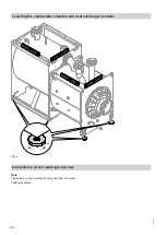
Installation without anti-vibration boiler supports
1.
Position a plate, e.g. a flat steel strip, underneath
the adjusting screws to distribute the load evenly.
2.
Fig. 6
Installation with anti-vibration boiler supports
To ensure the spring elements bear an equal load, pro-
vide a level installation area on site, with max. 1 mm
unevenness in the floor.
1.
Lift the combustion chamber module by the lifting
eyes.
2.
Position the anti-vibration boiler supports centrally
under the base rails.
3.
When setting the boiler down less than square on,
a boiler support can temporarily become overloa-
ded.
To prevent such overloading, position timbers
(ø 35 mm) under the base rails, evenly placed
between the boiler supports, to act as installation
aids.
4.
Position the combustion chamber module on the
anti-vibration boiler supports.
5.
Remove the timbers.
Installing the combustion chamber module
5833291
Summary of Contents for Vitocrossal CRU Series
Page 22: ...22 1 3 4 8 2 4x 3 5 2x 4 8 Fig 16 Fitting the crossbars 5833291...
Page 24: ...24 1 2 1 4 8 4 8 4 3 4 Fig 18 Fitting the side panels 5833291...
Page 26: ...26 4 A C M 6 x 20 B 2x 3 2x 1 2x 2 Fig 20 Fitting the top front panel cont 5833291...
Page 38: ...38 3 4x 4 2x 5 M6 x 10 2 1 4x Fig 32 Fitting the front side panels 5833291...
Page 40: ...40 4 2 5 1 2x 3 M 5 x 25 M 5 x 25 2x A Fig 34 A Type plate Fitting the front panel 5833291...
Page 41: ...41 Vitocrossal type CRU service instructions Commissioning 5833291...
Page 42: ...42 S System examples 5 Keyword index 5833291...
Page 43: ...43 5833291...


