Viessmann Vitocrossal 200 CM2C 115 Service Instructions Manual Download Page 12

12

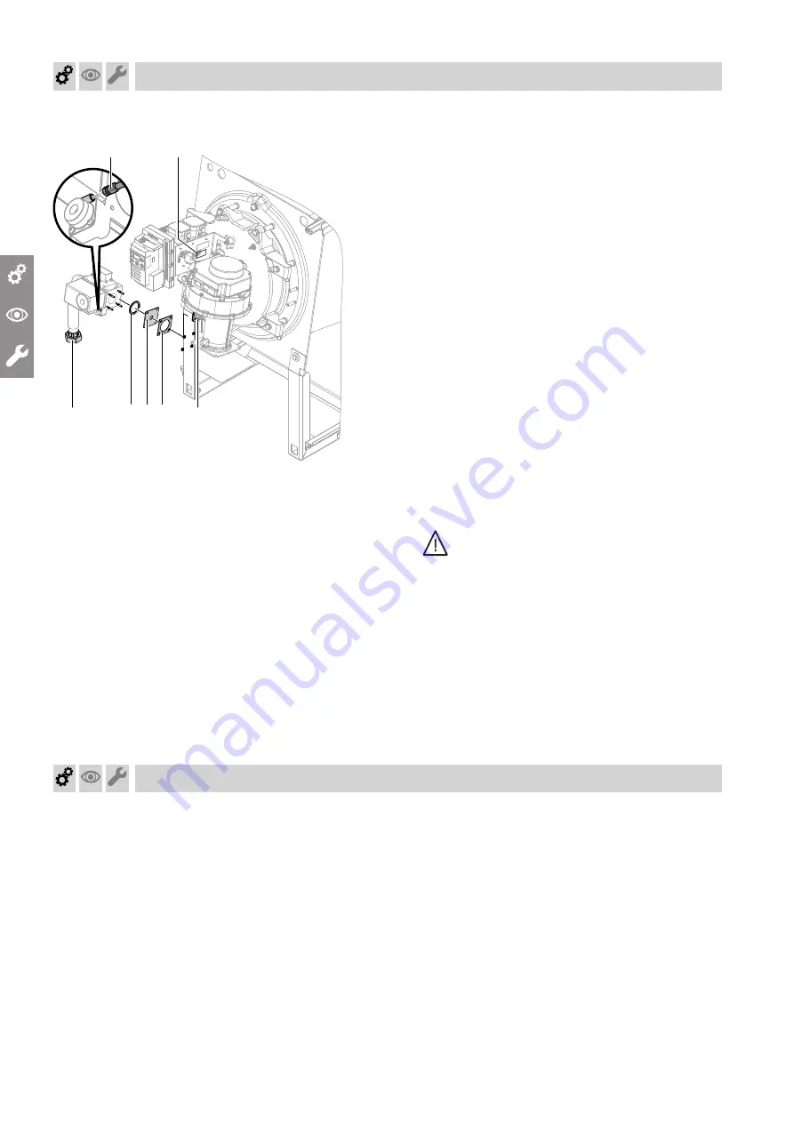
Conversion with 115 to 311 kW rated heating output

F

A

BCD

E

G

Fig. 3

0

1. 

Close the gas shut-off valve.

0

2. 

Switch off the system ON/OFF switch at the user
interface of the control unit.

0

3. 

Switch OFF the mains isolator (outside the instal-
lation room) or isolate the mains power and
secure against unintentional reconnection.

0

4. 

Undo fitting 

A

.

0

5. 

Disconnect control cable 

G

 from the gas train.

0

6. 

Release the gas train from flange 

E

.

0

7. 

Remove restrictor 

C

 with rubber cork gasket 

D

.

0

8. 

Secure the gas train to flange 

E

:

with O-ring 

B

without restrictor 

C

without rubber cork gasket 

D

Torque for M 5 nuts: 1.5 Nm

0

9. 

Secure fitting 

A

 with a new gasket.

10. 

Plug control cable 

G

 into the gas train.

11. 

Check control cables:

Connection and kink-free routing

Application and seating of retaining clips

12. 

Where present for set gas type: Affix label "Set
to ..." 

F

 supplied over the existing label.

13. 

Start the burner.

14. 

Check for gas tightness.

Danger

Escaping gas leads to a risk of explosion.
Check gas routing components for leaks.

!

Please note

The use of leak detection spray can result in
faulty operation.
Leak detection spray must not come into
contact with electrical contacts.

Note

For control cable locations, see page 27.

Conversion to LPG P

Conversion to LPG P only with 186 to 311 kW rated
heating output

Commissioning, inspection, maintenance

Conversion to natural gas L

 (cont.)

5831036

Summary of Contents for Vitocrossal 200 CM2C 115

Page 1: ...ons for contractors VIESMANN Vitocrossal 200 Type CM2C 75 to 311 kW Gas condensing boiler for open flue and room sealed operation Permissible operating pressure 6 bar VITOCROSSAL 200 5831036 GB 7 2019...

Page 2: ...st unintentional reopening Isolate the system from the power supply e g by removing the separate fuse or by means of a mains isolator and check that it is no longer live Safeguard the system against r...

Page 3: ...an be harmful to health Never let condensate touch your skin or eyes and do not swallow it Flue systems and combustion air Ensure that flue systems are clear and cannot be sealed for instance due to a...

Page 4: ...lts 45 Faults without fault display 46 5 Component overview Overview of burner components 48 MatriX radiant burner 75 and 87 kW 48 MatriX radiant burner 115 and 142 kW 48 MatriX cylinder burner 186 to...

Page 5: ...n Not required during inspection Steps required during maintenance Not required during maintenance Intended use The appliance is only intended to be installed and operated in sealed unvented heating s...

Page 6: ...lat ing MatriX cylinder burner for natural gas E LL and LPG P not CH Permissible operating pressure 6 bar See type plate for operation with other country specific gas types System examples Available s...

Page 7: ...ater side for tightness 22 19 Cleaning the condensate drain pipe and trap 23 20 Checking the condensate drain and neutralising system if installed 23 21 Checking the burner gauze assembly 24 22 Checki...

Page 8: ...ioning steps Inspection steps Maintenance steps Page 39 Instructing the system user 33 40 Operating and service documents 34 Commissioning inspection maintenance Steps commissioning inspection and con...

Page 9: ...m missioning 2 Check that the condensate can drain freely from the condensate drain hose Check the trap for leaks 3 If trap is leaking unscrew the lower part Check the gasket and replace if necessary...

Page 10: ...appear on the display 1 to acknowledge the fault message 2 to reset the burner Note The boiler can enter a fault state during commis sioning if the gas line carries insufficient gas Purge the gas line...

Page 11: ...ser interface of the control unit 03 Switch OFF the mains isolator outside the instal lation room or isolate the mains power and secure against unintentional reconnection 04 Undo fitting A 05 Release...

Page 12: ...e for M 5 nuts 1 5 Nm 09 Secure fitting A with a new gasket 10 Plug control cable G into the gas train 11 Check control cables Connection and kink free routing Application and seating of retaining cli...

Page 13: ...plied over existing label 14 Start the burner 15 Check for gas tightness Danger Escaping gas leads to a risk of explosion Check gas routing components for leaks Please note The use of leak detection s...

Page 14: ...Status 4 Press S On the display 1 appears under Status and the actual value for the maximum heating out put is shown in under Service 5 Use or to set the required maximum heating output 6 Press S to...

Page 15: ...re tester at test connector A 4 Open the gas shut off valve 5 Check the static pressure 6 Record the actual value in the report on page 55 Supply pressure Note See type plate for supply pressures for...

Page 16: ...ty or LPG supplier 18 to 50 mbar 1 8 to 5 kPa 42 5 to 57 5 mbar 4 2 to 5 75 kPa Start the boiler 50 mbar 5 kPa 57 5 mbar 5 75 kPa Install a separate gas pressure governor with zero off up stream of th...

Page 17: ...7 9 10 1 7 9 10 1 8 0 10 2 8 0 10 2 8 0 10 2 Actual value at upper heating output minus lower heat ing output 0 0 3 0 7 0 3 0 7 0 3 0 7 0 4 0 8 0 7 1 0 0 4 0 8 Natural gas LL upper heat ing output 100...

Page 18: ...ises Note The adjusting screw has no end stop 5 Enter actual value into the report in the appendix Checking the CO2 level at lower heating output 75 and 87 kW Fig 11 1 Press until the service indicato...

Page 19: ...ent falls Turning anti clockwise CO2 content rises 4 Enter actual value into the report in the appendix CO2 test at the lower heating output 115 to 311 kW Fig 13 1 Press until the service indicator ha...

Page 20: ...S 5 appears under Status 04 Press until 3 appears under Service 05 Press S 3 is shown under Status and during operation the ionisation current is shown under Service e g 30 3 0 A 06 Start the burner w...

Page 21: ...es on parts that come into contact with flue gas can corrode Only use plastic brushes no wire brushes or sharp objects For cleaning flush the heating surfaces thoroughly with a jet of water For stubbo...

Page 22: ...rain with trap KR Boiler return KR2 Boiler return 2 depending on version KV Boiler flow SA Safety connection A Fig 15 A Sensor well Note Also check the connections for the control equipment and the mi...

Page 23: ...agent can be ordered with part no 9521702 5 Undo and flush lower section D of trap B 6 Fill lower section D with water and secure 7 Reconnect drain hose to neutralising system A to trap B Route the d...

Page 24: ...ion ring B Installation instructions Replacing burner components Note If the specified rated heat input is not reached the burner gauze assembly is probably contaminated Clean the burner gauze assembl...

Page 25: ...d Installation instructions Replacing burner components 186 kW Ignition electrodes 5 2 1 7 0 5 3 5 0 5 Fig 21 Ionisation electrode 12 2 Fig 22 Check ignition electrodes and ionisation electrode for co...

Page 26: ...l connecting cables 100 and 100A from fan A Remove fan A Note Ensure that the gasket between the fan housing and the boiler door is correctly seated 5 Clean the fan housing and impeller carefully with...

Page 27: ...clips 6 Tighten fitting C on gas supply pipe D Danger Escaping gas leads to a risk of explosion Check the fitting and gasket between the fan housing and the boiler door for gas tight ness Please note...

Page 28: ...m 75 and 87 kW A B C D E F G L 35 L 120 L 326 L 302 L 370 L 230 L 533 L 260 L 280 L 590 L 520 Fig 28 A Gas train B Air pressure switch 1 C Air pressure switch 2 D Solenoid valve E Burner door F Fan G...

Page 29: ...L 105 L 400 Fig 29 A Gas train B Air pressure switch 2 C Air pressure switch 1 D Solenoid valve E Burner door F Venturi mixing pipe G Enriching nozzle 115 142 kW 1 mm 186 kW 0 5 mm 246 311 kW 1 mm H F...

Page 30: ...tor or thermal imaging camera for example In the case of leaks tighten crosswise to 30 Nm 3 To ensure that the boiler door closes tightly adjust the clearance between front panel and hinge bolt to 16...

Page 31: ...rs by tighten ing the respective screws Danger Escaping gas leads to a risk of explosion Check the test connectors for gas tightness Please note The use of leak detection spray can result in faulty op...

Page 32: ...seals A for tightness Note Check the gaskets at full load operation for exam ple using an inspection mirror dew point indicator or thermal image camera If required remove the thermal insulation secti...

Page 33: ...20 kPa higher 3 Top up with water The charge pressure of the cooled system must be 0 1 to 0 2 bar 10 to 20 kPa higher than the pre charge pressure of the expansion vessel Permiss operating pressure 6...

Page 34: ...m users their section for safekeeping Retain the heating contractor s section 2 File all parts lists operating and service instruc tions in the folder and hand this over to the system user Commissioni...

Page 35: ...on the boiler control unit Control unit installation and service instructions operating instructions Operating display In standard mode the status indicator shows the cur rent operating status The sam...

Page 36: ...ormation Menu point Description 1 Permanent meters for start ups and hours run 2 Resettable meters for start ups and hours run 3 Software version 4 Fault history for the last 10 fault codes Example to...

Page 37: ...n under Service 3 S 5 is displayed under Status 4 until 3 is shown under Service 5 S 3 is shown under Status under Service the ion isation current is shown during operation e g 30 3 0 A Menu point 6 i...

Page 38: ...5 S 1 is shown under Status and dEL under Service 6 S to confirm If reset successfully 1 is shown under Service if it failed 0 is shown 7 S to change to the operating display Manual operation and serv...

Page 39: ...omotor Ignition Fan PWM Fuel valve BV1 3 1 2 4 5 6 8 U System start Relay test Start up Operation Shutdown Fault states 9 7 C Waiting Standby F6 10 11 Code P Operation with flue gas damper Demand CAN...

Page 40: ...ier test max 50 s Gas fan and air pressure switch test max 20 s 2 Fan ramp up max 15 min 3 Pre purge 30 s Adjusting start up load test WD 1 25 s 4 Pre ignition 2 s 5 Safety time duration depends on bu...

Page 41: ...fault without displaying a fault code the fault memory may give an indication of the cause Call up the fault codes 1 S longer than 2 s flashes 2 until 4 is shown under Service 3 S 4 is displayed under...

Page 42: ...relay does not respond Reset or replace burner control unit F F3 Ionisation flame monitor re ports faulty flame signal dur ing start up or after the post purge Ionisation electrode or burner gauze as...

Page 43: ...gas back pressure condensate banked up air pressure switch 1 hoses faulty connecting hose leaking excessive pres sure drop on the supply air side Remove flue gas back pressure Check for backed up cond...

Page 44: ...ce on fan check flue outlet and fan Replace cable a A Replace fan Replace burner control unit F 80 Burner control unit in a fault state system cooling down burner control unit locked out Short circuit...

Page 45: ...d boiler heating output See Specification for connected values F F2 Burner control unit in a fault state system cools down Boiler water temperature limiter has responded Boiler water temperature too h...

Page 46: ...oltage e g DC voltage Actuator faulty Disconnect the plug from fuel valve 1 reset the burner control unit and check the fault messages If fault F Fd recurs replace the burner control unit 3A Ignition...

Page 47: ...icient draught in flue sys tem Check flue system Flame tears off during operation Intake strainer of gas train soiled Remove flange and clean strainer See page 31 Flue gas temperature too high Gas thr...

Page 48: ...re switch 131A P Air pressure switch 131 R Burner control unit S Ignition unit MatriX radiant burner 115 and 142 kW A B C D G F M L K H N O P B R D E Fig 38 A Boiler door B Display and programming uni...

Page 49: ...Fan D Gas supply pipe E Gas train F Venturi mixing pipe G Choke valve H Burner gauze assembly K Ionisation electrode L Ignition electrodes M Thermal insulation block N Air pressure switch 131A O Air p...

Page 50: ...5 50 87 115 1 100 142 186 246 311 Combustion chamber pressure monitoring air pressure switch 2 131A To monitor the combustion chamber pressure the switching threshold of air pressure switch 2 131A is...

Page 51: ...unit 3A 3B Boiler water temperature sensors 15A 15B Flue gas temperature sensors NTC 10 k 10 1 10 30 50 70 90 110 Temperature in C 0 4 0 6 0 8 2 4 6 8 20 Resistance in k Fig 41 Function description B...

Page 52: ...valve BV1 H Fan motor with PWM control and feedback K Display and programming unit L Air pressure switch 1 M Gas pressure switch N Air pressure switch 2 O Flue gas temperature sensor 1 P Flue gas tem...

Page 53: ...ill water and the water hardness into the boiler maintenance checklists For systems with a specific system volume greater than 20 l kW heating output apply the requirements of the next higher category...

Page 54: ...systems operating at the correct pressure e g systems with expansion ves sel offer good protection against the ingress of air borne oxygen Under all operating conditions and at all points in the heat...

Page 55: ...ng Total water volume Date m3 m3 m3 m3 Max fill volume m3 Water quality report Total hardness pH value Water treatment Date Feedwater Boiler water Boiler water Medium Dosing volume The pH value should...

Page 56: ...d heating output actual by vol set by vol at the lower rated heat ing output actual by vol set by vol Oxygen content O2 at upper rated heating output actual by vol set by vol at the lower rated heat i...

Page 57: ...th mm 660 660 660 660 760 760 760 Height mm 1178 1178 1178 1178 1277 1277 1277 Total dimensions Length mm 1774 1774 1774 1774 1793 1793 1793 Width mm 810 810 810 810 910 910 910 Height mm 1178 1178 11...

Page 58: ...cy to DIN For heating system tempera ture 40 30 C Up to 98 Hs gross cv For heating system tempera ture 75 60 C Up to 96 Hs gross cv Standby loss qB 70 0 6 0 6 0 5 0 4 0 4 0 3 0 3 MatriX burner Rated...

Page 59: ...2 0 kPa Natural gas K 2K G25 3 25 mbar 2 5 kPa Natural gas S 2S G25 1 25 mbar 2 5 kPa LPG P 3P G31 30 50 mbar 3 5 kPa Supply values combustion output relative to the max load with Natural gas E H G20...

Page 60: ...g 44 Rated heating output 115 to 311 kW Rated heating output kW Dim a mm Natural gas E LPG P 75 10 7 87 10 7 115 13 4 142 13 4 186 13 4 8 9 246 17 1 11 3 311 17 9 12 4 Specification Specification cont...

Page 61: ...ystem are not part of ordinary household waste For decommissioning isolate the system from the power supply and allow components to cool down where appropriate Dispose of all components correctly Fina...

Page 62: ...formity Manufacturer s certificate according to the 1st German Immissions Order BImSchV We Viessmann Werke GmbH Co KG D 35107 Allendorf confirm that the product Vitocrossal 200 type CM2C 75 to 311 kW...

Page 63: ...forming 33 Flow chart 39 Flow pressure 15 G Gas restrictor 59 Gas type check 11 Gas type conversion LPG P 12 Natural gas L 11 H Heating surfaces cleaning 21 Heating system Filling with water 9 I Ignit...

Page 64: ...Shropshire TF1 7YP GB Telephone 44 1952 675000 Fax 44 1952 675040 E mail info uk viessmann com Viessmann Werke GmbH Co KG D 35107 Allendorf Telephone 49 6452 70 0 Fax 49 6452 70 2780 www viessmann com...

Reviews: