background image

Installation instructions

for contractors

VIESMANN

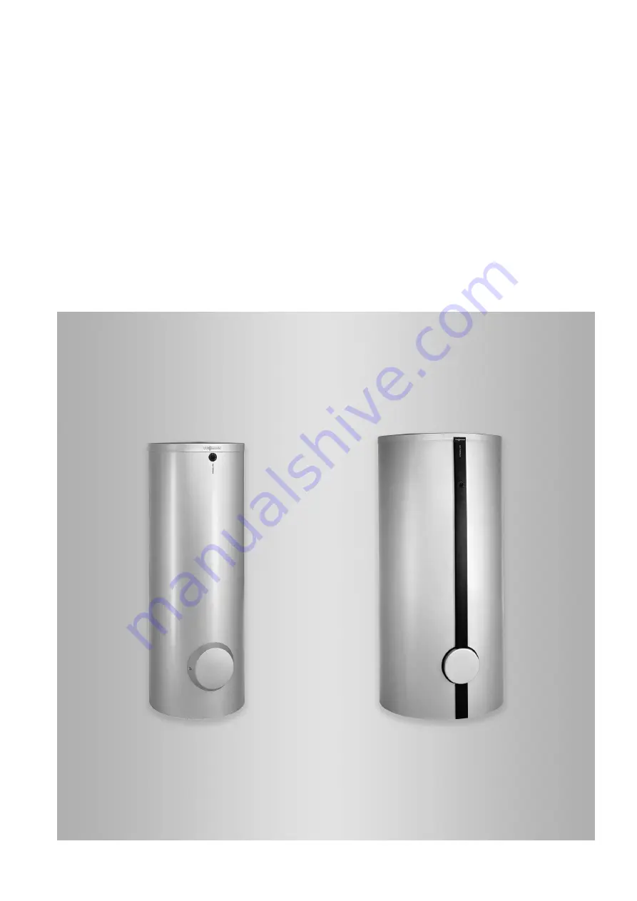
Vitocell 100-V
Type CVA, CVAA, CVAA-A

DHW cylinder, 160 to 950 l

Vitocell 100-W
Type CVA, CVAA, CVAA-A

DHW cylinder, 160 to 300 l

VITOCELL 100-V

VITOCELL 100-W

5813557 GB

8/2018

Dispose after installation.

Summary of Contents for CVA

Page 1: ...s for contractors VIESMANN Vitocell 100 V Type CVA CVAA CVAA A DHW cylinder 160 to 950 l Vitocell 100 W Type CVA CVAA CVAA A DHW cylinder 160 to 300 l VITOCELL 100 V VITOCELL 100 W 5813557 GB 8 2018 Dispose after installation ...

Page 2: ...y regulations as defined by DIN EN DVGW VDE and locally applicable standards a ÖNORM EN and ÖVE c SEV SUVA SVTI SWKI and SVGW Working on the system Isolate the system from the power supply e g by removing the separate fuse or by means of a mains isolator and check that it is no longer live Safeguard the system against reconnection Wear protective clothing Please note Electronic assemblies can be d...

Page 3: ...ction 10 Siting DHW cylinders 750 to 950 l 11 Siting the DHW cylinder and checking the anode connection 11 Fitting the thermometer sensor if supplied and cylinder tempera ture sensor 12 Thermal insulation 500 to 950 l 13 Fitting the thermal insulation jacket 13 Fitting the thermometer if supplied thermometer sensor and cover strips 14 Fitting the cover 15 500 l DHW cylinders 16 Fitting the cylinde...

Page 4: ...cument containing further information 1 Step in a diagram The numbers correspond to the order in which the steps are carried out Warning of material losses and environ mental pollution Live electrical area Pay particular attention Component must audibly click into place or Acoustic signal Fit new component or In conjunction with a tool Clean the sur face Dispose of component correctly Dispose of c...

Page 5: ...rial usage for a purpose other than heating the building or DHW shall be deemed inappropriate Any usage beyond this must be approved by the man ufacturer for the individual case Incorrect usage or operation of the appliance e g the appliance being opened by the system user is prohibi ted and results in an exclusion of liability Incorrect usage also occurs if the components in the system are modifi...

Page 6: ...ermal insulation must not come into con tact with naked flames Exercise caution when welding and brazing Please note To prevent material losses site the DHW cylin der in a room free from the risk of frost and draughts Alternatively drain the DHW cylinder when not in use and there is a risk of frost Allow an adequate distance from the wall to enable the temperature controller if supplied to be oper...

Page 7: ...ersion heater installed on site must be at least 100 mm The threaded immersion heater must be suitable for installation in enamelled DHW cylinders Cylinder capacity Output of im mersion heater Dim a in mm 300 l 6 kW min 685 500 l 6 kW min 650 750 l 950 l 6 kW min 650 750 l 950 l 12 kW min 950 Siting 300 l DHW cylinders with heating lance 585 Fig 4 Preparing for installation cont 5813557 ...

Page 8: ... of the sensor retainer contact spring not in the groove so that it is flush with the front of the spring Never wrap insulating tape around the sensor Insert the sensor retainer together with the sensor as far as they will go into the sensor well Insert the thermometer sensor as far as it will go into the clamping bracket on the flange cover Siting DHW cylinders up to 300 l 5813557 ...

Page 9: ...tion fitting the fascia and cover affixing the type plate 3 4 2 A B 1 Fig 6 A Magnesium anode B Earth cable Note Guide the thermometer lead through the groove in the flange insulation Siting DHW cylinders up to 300 l cont 5813557 ...

Page 10: ...10 Fitting the thermal insulation and checking the anode connection 2 A B 3 1 Fig 7 A Magnesium anode B Earth cable Siting DHW cylinders 500 l 5813557 ...

Page 11: ... anode B Earth cable Note Check that the earth cable is connected to the magne sium anode Insert the adjustable feet into the legs as far as they will go and use them to level the DHW cylinder Never extend the adjustable feet beyond a total length of 35 mm Siting DHW cylinders 750 to 950 l 5813557 ...

Page 12: ... and insert it as far as it will go into the clamp ing bracket on the flange Note The cover strip is held in its vertical position by the unwound capillaries This is necessary for the rest of the installation 3 Route the cylinder temperature sensor to the back of the DHW cylinder 4 Release the nuts 5 Push the clamping device onto the threaded studs and align 6 Tighten the nuts 7 Push the cylinder ...

Page 13: ...left sections of the thermal insulation jacket and place it around the cylinder body Note Leave the clip fasteners in the first notch 2 At the front of the cylinder Attach 6 clip fasteners to the edges of the right and left sections of the thermal insulation jacket 3 Push the clip fasteners at the back of the cylinder as close together as possible 4 Push the clip fasteners at the front of the cyli...

Page 14: ...or 500 l Guide the thermometer lead through the front cover strip and thermal insulation jacket Note If no thermometer is being installed seal the hole with a cover pipe collar 3 For 500 l Insert the thermometer sensor as far as it will go into the clamping bracket 4 Fit the flange cover 5 Fit the front cover strip 6 Fit the back cover strip 7 Affix the type plate Thermal insulation 500 to 950 l c...

Page 15: ...15 Fitting the cover 1 2 A 3 Fig 12 A Viessmann logo Thermal insulation 500 to 950 l cont 5813557 ...

Page 16: ... Never wrap insulating tape around the sensor Insert the sensor retainer with sensor into the sensor well as far as it will go Preparing a multi cylinder bank 300 and 500 l Dimensions of the connections of Viessmann headers accessories Capacity per cylinder l 300 500 Number of cylinders 2 2 3 Connections Heating water flow and return DN 50 50 50 Cold water DHW R 1 1 1 DHW circulation R 1 1 1 500 l...

Page 17: ...ures that every cylinder is heated and that water is drawn off from every cylinder equally Connections on the heating water side Connect all pipework with detachable fittings Seal any connections that are not required with red brass caps Adjust the temperature controller and high limit safety cut out so that the DHW temperature in the DHW cylinder does not exceed 95 C Individual cylinder Cylinder ...

Page 18: ... above 110 C If the system does not already have one also install a type tested high limit safety cut out For this use a TR STB temperature limiter and high limit safety cut out Connections on the DHW side For connections on the DHW side observe DIN 1988 and DIN 4753 Connect all pipework with detachable fittings Seal any connections that are not required with red brass caps Equip the DHW circulati...

Page 19: ...ut off from the DHW cylinder There must be no constrictions in the pipework between the safety valve and the DHW cylinder Never seal off the safety valve discharge pipe Ensure that any expelled water is safely and visibly drained into a drainage system Position a sign close to the safety valve discharge pipe or ideally on the safety valve itself with the fol lowing inscription For safety reasons w...

Page 20: ...old water WW DHW Z DHW circulation pipe CP DHW circulation pump Connecting the equipotential bonding Connect the equipotential bonding in accordance with the requirements stipulated by your local power supply utility and VDE or local regulations CH Connect the equipotential bonding in accordance with the technical requirements stipulated by your local power supply utility and SEV regulations Commi...

Page 21: ...n mm 1189 1409 1734 1948 1897 2197 Excl thermal insulation mm 1844 1817 2123 Height when tilted Incl thermal insulation mm 1260 1460 1825 Excl thermal insulation mm 1860 1980 2286 Entire weight incl thermal in sulation kg 86 97 156 181 301 363 Connections male thread Heating water flow and return R 1 1 1 1 1 1 Cold water DHW R 1 1 1 1 DHW circulation R 1 1 1 1 Immersion heater EHE Current type and...

Page 22: ...earance for the installation of an immersion heater EHE 2 4 6 kW mm 685 650 650 650 4 8 12 kW mm 950 950 Weight Vitocell 100 V kg 156 181 301 363 Immersion heater EHE 2 4 6 kW kg 2 2 2 2 4 8 12 kW kg 3 3 Heating lance accessories DHW cylinders Vitocell 100 V W type CVAA 300 l Content that can be heated with the heating lance 248 l Specification cont 5813557 ...

Page 23: ...23 5813557 ...

Page 24: ... Shropshire TF1 7YP GB Telephone 44 1952 675000 Fax 44 1952 675040 E mail info uk viessmann com Viessmann Werke GmbH Co KG D 35107 Allendorf Telephone 49 6452 70 0 Fax 49 6452 70 2780 www viessmann com 5813557 Subject to technical modifications ...

Reviews: