73
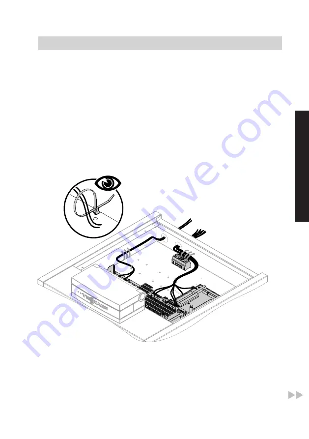
■ Route LV leads < 42 V and
cables > 42 V/230 V~/400 V~
separately.
■ Strip the insulation from the
cables as close to the terminals
as possible, and bundle tightly
to the corresponding terminals.
■ Secure cables with cable ties.
This ensures that, should there
be an error, for example when
detaching a wire, the wires can-
not drift into the adjacent voltage
area.
When routing the on-site power cables,
observe the location of the cable entries
into the appliance through its back panel
(see page 11).
< 42 V
230 V
1.
Route LV leads through the "< 42 V"
aperture to the heat pump control unit
wiring chamber and apply strain relief
using the cable ties provided.
2.
Route 230 V~ cables and power
cables for the compressor through
the "230 V~" aperture to the heat
pump control unit wiring chamber and
apply strain relief using the cable ties
provided.
Installation sequence
Electrical connections
(cont.)
5609 667 GB
Installation


