Chapter 2
Using the TC-201A
General Operating Procedure
Final
TC201-A Operation Manual
Release Num. 000
Page 8
December 2019
General Operating Procedure
The following general procedure is suggested for using the TCAS Coupler to verify TCAS
power and quadrant accuracy. This procedure is presented as a supplement to the
recommended test procedure in the Ramp Test Set Operation Manual. Specific
requirements and operation settings for the various TCAS displays, antennas, and Mode
S equipment are not addressed in this procedure. Refer to the Ramp Test Set Operation
Manual and UUT manual for specific testing guidelines.
Aircraft Setup
The aircraft may be configured to “in the airborne condition” before testing can be
performed. A transponder test can be performed with the aircraft in the Airborne or Surface
condition. Please refer to aircraft specific information to complete this step. The following
are some common required settings:
•
Weight off wheels
•
Air Data set for altitude of 10,000 ft and airspeed of 300 kts.
•
RadAlt Antennas covered. (speed tape)
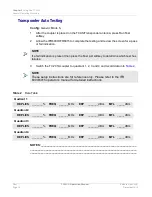
Testing Using TC-201A
1
Connect the TC-201A to the IFR-6000 Antenna Port using the supplied cable and the
30dB attenuator.
2
Set the TC-201A to Quadrant 1.
XPDR Setup
ANTENNA
Top
RF PORT
Antenna
ANT RANGE
See coupler loss label
ANT HEIGHT
See coupler loss label
ANT CABLE LEN
Length of cable used
ANT GAIN (dBi)
ANT Cable Loss
See cable loss label
0.96 GHz
0.0
Coupler Loss
0.0 dB
1.03 GHz
0.0
UUT ADDRESS
AUTO
1.09 GHz
0.0


