background image

ONX-220 User's Guide

22135173, Rev. 000

June 2020

135

Chapter 

9  Configuring the OneExpert with StrataSync

Tilt Settings

Titl Settings allows you to set the low and high frequencies for tilt (85–1218 MHz).

Tilt Settings Configuration

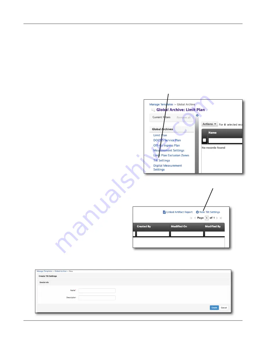
You can find Tilt Settings through the 

Global Archives

 pane on the left side of the 

StrataSync Manage Templates screen. The Tilt Settings screen appears.

New Tilt Settings

1.  From the Tilt Settings screen, select the 

New Tilt Settings

 button on the 

upper right of the screen. The Create 

Tilt Settings screen appears.

2.  Enter the name (required) and 

description if desired.

3.  Select the 

Create

 button. The Tilt 

Settings template appears.

Tilt Settings

New Tilt Settings

Summary of Contents for ONX-220

Page 1: ...ONX 220 User s Guide ...

Page 2: ...elease Reproduction and distribution of this guide is authorized for US Government purposes only Ordering information This guide is a product of the VIAVI Technical Publications Department issued as part of the product You can obtain the manual through StrataSync A printed quick start guide also ships with the instrument and can be downloaded through StrataSync Terms and conditions Specifications ...

Page 3: ...quipment CAUTION y This equipment complies with FCC radiation exposure limits set forth for an uncontrolled environment The End user must follow the specific operating instructions for satisfying RF exposure compliance y This transmitter must not be co located or operating in conjunction with any other antenna or transmitter Industry Canada Requirements This device complies with Industry Canada li...

Page 4: ...ndards and Policies web page If you have questions concerning disposal of your equipment or batteries contact the VIAVI WEEE Program Management team at WEEE EMEA ViaviSolutions com EU REACH Article 33 of EU REACH regulation EC No 1907 2006 requires article suppliers to provide information if a listed Substance of Very High Concern SVHC is present in an article above a certain threshold For informa...

Page 5: ...er birth defects or other reproductive harm For the VIAVI position statement on the use of Proposition 65 chemicals in VIAVI products see the Hazardous Substance Control section of the VIAVI Standards and Policies web page Compliance with 2014 53 EU Radio Equipment Directive RED In accordance with Article 10 8 a and 10 8 b of the RED the OneExpert DSP instruments for sale in the EU operates in the...

Page 6: ...nstalled at the VIAVI factory or by VIAVI approved repair facilities During operation of the device a distance of 20 cm or more should be maintained between the antenna in this device and person To ensure compliance do not operate at closer distances than this The antenna on the unit is located inside the device at the top of the unit attached to the back plastic case Do not use any antenna other ...

Page 7: ...v 000 June 2020 7 Precautions continued CAUTION Use only the battery charger supplied with the meter Use of any other charger may damage the battery NOTE All spent batteries should be disposed of according to local laws and guidelines ...

Page 8: ...ONX 220 User s Guide 22135173 Rev 000 June 2020 8 ...

Page 9: ...nu conventions 21 Symbol conventions 21 Symbol conventions continued 22 Safety Definitions 22 What ships with the ONX 220 23 Preparation for use 23 Available models 23 Chapter 1 Quick Tour 25 About the ONX 220 26 Benefits 26 Key features 26 Connected 27 Flexible and affordable 27 Efficient 27 A guided tour of the ONX 220 28 Front view 28 Bottom view 29 Status indicators 30 Touchscreen display 30 S...

Page 10: ...39 Change the time zone 39 Control Time Synchronization 39 Changing screen and power settings 40 Set the backlight 40 Set the backlight timeout 40 Set the power off delay 40 Setting the volume 41 Specifying the location for saved files 41 Specifying user information 41 Restoring factory defaults 42 Establishing network connections 42 Enabling network connectivity 42 Establishing an Ethernet connec...

Page 11: ...wing a report 58 Viewing your work orders 59 Editing work orders 62 Saving a report to a work order 63 Work order notifications 64 Workflow settings 64 Managing files 65 Accessing the file browser 65 Selecting files or folders 65 Opening files or folders 65 Copying and pasting files or folders 66 Uploading files using FTP HTTP 66 Managing files with StrataSync 66 Viewing the User s Guide on your i...

Page 12: ...ard 76 Drill Down 76 Pass Fail Indication 76 Channel View 77 Measurement Pass Fail Indication 77 Chapter 4 CATV Testing 79 CATV Test Options 80 OneCheck 80 To run a OneCheck Test 81 Cable Fault Finder and HL Leakage optional 82 Results 82 Saving Results 82 Ingress Scan 83 To run an Ingress Scan 83 Results 83 ChannelCheck 84 To run a ChannelCheck 84 Results 84 Saving results 84 DOCSIS Check 85 To r...

Page 13: ... test profiles 96 Connecting to the line 96 Viewing results 96 Testing the data layer 97 Chapter 6 Data Testing 99 About Data Tests 100 Ping and Traceroute testing optional 100 Speed Check testing optional 101 Apache server setup 101 Server scaling 104 Server over provisioning 104 Chapter 7 Fiber Testing 105 About the optical tools 106 Inspecting fiber 106 Measuring optical power 108 Chapter 8 WiF...

Page 14: ...127 Measurement Settings 128 Measurement Settings Configuration 128 New Measurement Settings 128 OneCheck Settings 129 Viewing Editing Renaming or Deleting a Measurement Plan 130 Saving Measurement Settings 130 Measurement Settings Deployment 131 Limit Plan Exclusion Zones 132 Limit Plan Exclusion Zone Configuration 132 New Limit Plan Exclusion Zones 132 Limit Plan Exclusion Zone Configuration 133...

Page 15: ...n Template Configuration 147 New Channel Plan Template 147 Channel Plan Template Settings 148 Viewing Editing Renaming or Deleting a Channel Plan Template 148 Saving Channel Plan Templates 148 Channel Plan Template Deployment 149 Throughput URL Settings 150 Throughput URL Settings Configuration 150 New Throughput URL Settings 150 Throughput URL Settings 151 Viewing Editing Renaming or Deleting Thr...

Page 16: ...75 ChannelCheck results 176 QAM Channels 176 OFDM Channels 176 Dashboard 177 Channel View 177 QAM Channels 177 OFDM Channels 178 Spectrum IUC 179 Level Over Time optional 179 MER Over Time optional 179 BER Over Time optional 179 DQI Over Time optional 180 ICFR In Channel Frequency Response optional 180 Tilt 180 SmartScan optional 180 Favorites 181 Constellation 181 Level Variation OFDM 182 MER Var...

Page 17: ...ng 189 Quick Check results 189 Cable Fault Finder results 190 Drop Check 190 Cable Length 190 Changing the display 191 Zooming 191 Panning 191 Changing Cable Type 191 Moving the markers 191 Adding a second marker 191 Stopping the test 192 StrataSync reports 192 HL Leakage results 193 Equalizing the signal 193 Adjusting the volume and mute 193 StrataSync reports 194 Spectrum results 195 Moving the ...

Page 18: ...ntents Chapter 12 Appendix 199 Cleaning the instrument 200 Resolving problems 200 General testing 200 Data testing 200 Limited warranty 201 Getting technical assistance 201 Additional information 201 Specifications 202 Ordering information 206 Feature matrix 207 ...

Page 19: ...f the VIAVI warranty services and repair information Assumptions This guide is intended for novice intermediate and experienced users who want to use the product effectively and efficiently We are assuming that you have basic computer and mouse track ball experience and are familiar with basic telecommunication concepts and terminology Technical assistance If you require technical assistance call ...

Page 20: ...ns as described in the following tables Description Example User interface actions On the Status bar click Start Buttons or switches that you press on a unit Press the ON switch Code and output messages All results okay Text you must type exactly as shown Type a set exe in the dialog box Variables Type the new hostname Book references Refer to Newton s Telecom Dictionary A vertical bar means or on...

Page 21: ... See the Safety Definitions on page 22 for more information This symbol represents an alert It indicates that there is an action that must be performed in order to protect equipment and data or to avoid software damage and service interruption This symbol represents hazardous voltages It may be associated with either a DANGER WARNING CAUTION or ALERT message See the Safety Definitions on page 22 f...

Page 22: ...ll result in death or serious injury It may be associated with either a general hazard high voltage or other symbol WARNING Indicates a potentially hazardous situation that if not avoided could result in death or serious injury It may be associated with either a general hazard high voltage or other symbol CAUTION Indicates a potentially hazardous situation that if not avoided could result in minor...

Page 23: ...cal assistance on page 19 y If undamaged save the box and packing materials in case you need to ship the instrument in the future y Remove the protective film from the LCD This film is in place to protect the LCD during shipment Use the tab in the lower right corner to easily remove the film Before using the OneExpert for the first time do the following y Turn the OneExpert on use the green button...

Page 24: ...ONX 220 User s Guide 22135173 Rev 000 June 2020 24 About this Guide NOTE This hand held instrument is not intended to be body worn or operated while held against the body ...

Page 25: ...apter provides an overview of the unit status indicators connectors and user interface including the following y About the ONX 220 on page 26 y A guided tour of the ONX 220 on page 28 y Navigating the user interface on page 31 y Personalizing the user interface on page 33 ...

Page 26: ...ccess to a rugged precise measurement instrument at a budget minded price y Best balance of features performance and cost designed to meet the budgets of installers and contractors Key features y AutoChannel instantaneous channel lineup detection eliminates need for lineup editing updating and deploying y OneCheck comprehensive mistake proof automated tests including ingress downstream channels an...

Page 27: ...nspection and power measurements along with home network integrity testing Efficient y Simple icon based UI with capacitive touch screen control is easy for new technicians to learn y Powerful measurement dashboards with simple Pass Fail results for novice technicians while advanced techs can drill down for more detailed measurement results y Technicians can quickly identify and resolve issues wit...

Page 28: ...20 User s Guide 22135173 Rev 000 June 2020 28 Chapter 1 Quick Tour A guided tour of the ONX 220 Touchscreen Softkeys Back button Power button Water resistant speaker RF connector Status indicators Front view ...

Page 29: ... NOTE In the image above the protective rubber door is in the open position for illustrative purposes This door should remain closed when not using any of these ports Bottom view Ethernet Port 10 100 1000 Mbit s USB 3 0 Port Type A USB C Charge Port Protective Rubber Door ...

Page 30: ... the unit for repair contact VIAVI for an RMA WiFi Indicates the WiFi radio status Bluetooth Indicates the Bluetooth radio status Modem Online Indicates the DOCSIS modem status UP Indicates the upstream mode DN Indicates the downstream mode Touchscreen display The touchscreen display operates similar to a smart phone or tablet where you swipe to go to the next page or zoom in out by pinching or op...

Page 31: ...r to a mobile device such as an iPad or similar Android device where you swipe to go to the next page or zoom in out by pinching or opening your fingers Using the interface you can view test results set up the ONX and configure test parameters When you power up the ONX 220 the Home screen appears The Home screen indicates the options enabled on your instrument Collapsible menu Rearrange icons Quic...

Page 32: ...wn to show the menu is expanded Selecting a menu option After you expand a collapsible menu you can select a specific option by pressing the menu option Using the tray menu The Tray menu allows access to commonly used functions It can be accessed by swiping downward from the top of the screen Save Report Saves the results to a report Formats available XML PDF or HTML View Reports Views a saved rep...

Page 33: ...tton on the onscreen keypad The data is entered and stored Personalizing the user interface If you have a test or function that you use frequently you can make it a shortcut You can create up to four shortcuts Shortcuts y To create a shortcut press and hold the icon for the function and then drag it to the bottom of the screen to the shortcut bar y To remove a shortcut press and hold the icon and ...

Page 34: ...ONX 220 User s Guide 22135173 Rev 000 June 2020 34 Chapter 1 Quick Tour ...

Page 35: ...lowing y Accessing system utilities on page 36 y Setting up your instrument on page 38 y Restoring factory defaults on page 42 y Establishing network connections on page 42 y Establishing a Bluetooth connection on page 47 y Updating the instrument s firmware on page 48 y Synchronizing to the StrataSync server on page 55 y Viewing your work orders on page 59 y Managing files on page 65 y Managing f...

Page 36: ...System Settings menu Using the items provided on the System Settings menu you can turn on remote operation via VNC Viewer change screen and power settings control the volume view hardware and software versions view options purchased with the ONX 220 meter and complete USB software updates 1 From the Main menu press the System menu item 2 Press the System Settings icon The System Settings menu appe...

Page 37: ...Tray menu you can specify settings required for network WiFi and Bluetooth connectivity control the volume on your instrument and manage job tickets and reports You can also take screenshots of the user interface and review a PDF of this guide on your instrument To bring up the Tray menu swipe downward from the top of the screen ...

Page 38: ...onal settings to take effect The settings will be retained when you turn your instrument off 1 Go to the System Settings menu then select International Settings The International Settings menu appears 2 Optional Select Country to select a preset country Selecting a specific country will automatically change the settings as appropriate for that country For example selecting France will automaticall...

Page 39: ...calendar 4 Press Set Specify the date format 1 Press Date Format 2 Select MM DD YYYY or DD MM YYYY Specify the time format 1 Press Time Format 2 Select 12 Hour or 24 Hour Change the time zone 1 Press Time Zone 2 Select the time zone 3 If Daylight Savings Time DST is used in your area press the DST Used checkbox to enable DST A check mark will appear indicating that DST is enabled Control Time Sync...

Page 40: ...e refers to time during which no keys are pressed and no line activity takes place So if you set the Power Off Delay to 5 minutes and then begin a 15 minute test the unit will not power down during the test because there is activity on the line as a result of the test Go to the System Settings menu then select Screen Power Management NOTE The OneExpert will not automatically power down when connec...

Page 41: ...nu then select Save Location 2 Press the circle to the left of File System USB device when available or Both when applicable 3 Press the Back Cancel button to save and exit the menu Files will be saved to the location and or device specified Specifying user information The User Information menu allows you to enter specific information related to the technician using the OneExpert This includes the...

Page 42: ...ng network connections You can establish wired network and intranet connections and wireless WiFi connections to your instrument to update the firmware transfer files synchronize to the StrataSync server or control the instrument s user interface remotely Enabling network connectivity Before you establish a connection to an Ethernet or WiFi network you must enable network connectivity on your inst...

Page 43: ...e required to connect to the LAN 4 Select Network Mode and then specify the network mode IPv4 IPv6 or IPv4 IPv6 Dual Stack Depending on the Network Mode you have one or more additional settings to specify 5 Configure the instrument s IP settings to match the LAN settings by doing one of the following y If you specified IPv4 as your network mode specify the following settings IPv4 Address Mode DHCP...

Page 44: ... route packets that are not on the same subnet IPv6 DNS Address Mode y DHCPv6 No additional settings to specify y Manual Enter the IPv6 DNS Server address IPv6 DNS Server Enter the address of the DNS server y If you specified IPv4 IPv6 Dual Stack as your network mode specify the following settings IP Dual Stack Address Modes DHCP No additional settings to specify Static See the IPv4 Address Mode i...

Page 45: ... and establish a connection to the network if 1 network connectivity is enabled 2 the network s access point is in range and 3 the network is determined to provide the best available access point based on signal strength and or encryption supported The instrument can save up to 32 WiFi network profiles NOTE Your instrument will automatically save a profile after successfully connecting to a new Wi...

Page 46: ... profile for the network has been saved on your instrument and a connection can be established to the instrument y Saved Out of Range A profile for the network has been saved on your instrument but the network is out of range and therefore a connection cannot be established y Incompatible A connection cannot be established to a network y Connected The instrument has already established a connectio...

Page 47: ...ync from the Mobile Tech App on page 154 Connecting to a Bluetooth device You can establish a connection to any Bluetooth device that is within range of your instrument and for which you have authorized access 1 Go to the System Settings menu then select Bluetooth The Bluetooth Settings menu appears 2 Press the box next to Enabled A checkmark appears 3 Press Scan for devices The instrument scans f...

Page 48: ... its best The OneExpert CATV firmware can be updated in the field using a wired network or intranet connection or a USB drive with a copy of the firmware Download the firmware to a USB drive If you are using a USB drive for updates you can download the firmware from StrataSync This is the preferred download method NOTE You need to have permissions to update units in order to download software from...

Page 49: ...ate Firmware window scroll to the right and click the Download Firmware link The file will begin to download 6 Once file has been downloaded plug in the USB drive and copy the firmware file to the root directory The file name will be similar to ONXCBL xxx xxx xxx oxu Download firmware ...

Page 50: ... update 2 Disconnect any Ethernet cables connected to the unit 3 Plug the USB drive that you downloaded the firmware file to into a USB port on the OneExpert 4 Go to the System Settings menu then select USB Software Update 5 In the pop up menu select the desired firmware file on the USB drive 6 Press the Update button then press it again to confirm The update will begin and the meter will power of...

Page 51: ...r instrument to the intranet or network 3 Verify the ONX has a valid IP address it should have been changed from the default address of 192 168 0 4 Go back to the Home screen scroll down to the bottom and select StrataSync 5 On the StrataSync screen enter the following y StrataSync Account ID Determined at Setup y Interface Ethernet DOCSIS If set to DOCSIS firmware upgrades will be skipped without...

Page 52: ...wait as this could take 10 15 minutes based on the size of the update file and connection speed Troubleshooting the Upgrade Process No IP address 1 Navigate to the System Network Profiles screen System menu Network icon 2 If the IPV4 State shows In Use By Application via the Home screen navigate to the Ethernet menu and select the Ethernet icon 3 Select the Network Stop button at the bottom This d...

Page 53: ...e update via USB Viewing hardware software versions and options The following procedure describes how to view the status of available options and the hardware and software versions for your instrument 1 Go to the System Settings menu 2 Do one of the following y To review hardware and software versions select Hardware Software Revisions The revisions of the internal components and the software vers...

Page 54: ...us sections If you received the option file by email instead of a USB drive save the option file to a USB drive 2 Insert the USB drive into the OneExpert 3 From the main menu press the System menu item The collapsible menu opens 4 Select USB File Browser 5 Highlight the option file on the USB drive 6 Select File Option and then Copy to Internal The file is copied to the internal file browser 7 Pre...

Page 55: ...nfigurations y Manage OneExpert homescreen settings via templates To obtain the latest configuration settings software options and updates and ownership registration information the OneExpert CATV can synchronize with a VIAVI server via the internet The synchronization also stores any user files saved on the unit to the StrataSync server This procedure should be undertaken immediately upon receipt...

Page 56: ...s is https stratasync viavisolutions com y Server Port Enter the server port number The default port is 443 6 Press the Start button As the process runs the sync state is displayed on the screen y Upon synchronization with the StrataSync server the unit will send to the server the following information The unit s serial number The unit s hardware information constituent assemblies and their revisi...

Page 57: ...chronization is complete the Status will indicate Sync Complete The unit may be disconnected from the server Generating reports The Save Report icon provided on the Tray menu allows you to create reports based on the configuration settings and test results for the currently active test This only works for Ethernet tests Saving a report If you are currently running a test you can save test results ...

Page 58: ...the last time you saved the report Viewing a report You can view saved reports on the LCD of your instrument 1 Access the Tray menu and then press View Report A View Report screen appears showing all of the saved reports 2 Select a report to view The report appears on the screen NOTE If the View Report icon is disabled gray there are no reports saved on your instrument Capturing a screen shot In a...

Page 59: ... System main menu select Workflow Manager You can also bring up Workflow Manager from the Tray menu With the workflow option in StrataSync each tech s meter can be updated with a day s workorders enabling a tech to choose the workorder that matches the current task perform the prescribed tests and close it out with data uploaded for management with a smooth simple process Get confirmation that tec...

Page 60: ...is as follows 1 Deploy profiles configuration files to instruments via sync as part of standard procedure 2 Create work orders and reference techId and test profile 3 Deploy work order to instrument with test profile reference 4 Sync to StrataSync with work order info after testing and saving CDM reports JSON 5 View test results associated work order on StrataSync and or contractor transfer to cus...

Page 61: ...and reporting features that are enhanced through StrataSync This helps to ensure complete test processes for performance to standards and to minimize return service calls Report example List of assigned work orders List of required tests for selected work order Test status indicated Work order data report saved ...

Page 62: ...der you want to edit The work order opens and displays information as well as tests to be run that may have been deployed from StrataSync Some of the information and tests will be grayed out depending if they are required or how how they were set up in StrataSync 3 To edit information for the work order select Information to add comments location ID or circuit number etc 4 To create a new work ord...

Page 63: ...r incomplete 7 To delete a work order use the arrows to select the work order then select Delete If the work order is active it will be deactivated first You can also run a test from any configuration screen by pressing the Launch Test button This also automatically activates the work order Saving a report to a work order Any reports you create will be saved to the active work order unless you cho...

Page 64: ...what your company uses 1 From the Tray menu select Workflow Settings at the bottom Workflow Manager needs to be running to see this 2 From the Workflow Settings screen select the setting you want to edit and adjust as necessary Work order notifications When work orders are added from StrataSync the Mobile Tech app or via USB you ll see a notification in the Tray menu with the details ...

Page 65: ...ected USB flash drive press the USB File Browser button The File Browser menu appears listing all folders or files Selecting files or folders 1 Go to the file browser 2 Use the up and down arrow buttons to move among folders or files to see the contents of a folder press the folder 3 Do one of the following y To select a single file or folder press the checkbox to the left of the file or folder y ...

Page 66: ...s Uploading files using FTP HTTP 1 Go to the file browser 2 Select the file or folder 3 Press the File Options system key and then select Upload FTP HTTP The upload settings appear 4 Specify the upload URL username and password 5 Press Apply The upload starts When the upload finishes a message appears stating that the selected files were uploaded Press OK to close the message Managing files with S...

Page 67: ... network connection VNC connecting over an Ethernet interface or WiFi network The is a great way to capture screens shots for additional troubleshooting etc To use this feature 1 you must have a VNC viewer program on the PC or mobile device 2 the OneExpert must be connected to the same network as the PC or device and 3 you must know the IP address of the OneExpert Establishing a VNC connection inv...

Page 68: ...ith your ONX and connect to it remotely you need to enable VNC in System Settings 1 Go to the System Settings menu then select Remote Operation The Remote Operation menu appears 2 Select VNC The VNC menu appears 3 Select Enable VNC Server and note the VNC password underneath viavi vnc You will need it to connect via VNC Viewer ...

Page 69: ... address field enter the OneExpert s IP address and click OK A password entry box appears 3 Enter the VNC password you noted before viavi vnc found in the Remote Operation menu and then click OK The OneExpert user interface appears in the VNC viewer and works similarly to using the unit itself See the next section for details 4 If the message Failed to connect to server appears the VNC viewer was ...

Page 70: ...s how the PC keys map to the OneExpert keypad PC key OneExpert key F1 F4 Correspond to the OneExpert system keys F5 Home F6 Tray menu F7 AutoTest Escape Cancel Enter OK VNC availability In Ethernet you can do a ping trace route and similar data tests but you cannot change any data settings Ending a remote operation session To end a remote operation session either exit the VNC session on the PC or ...

Page 71: ... cannot log into a web mail account The browser does not currently support Java applets and will not display web pages written in Java Sites optimized for quick downloads such as DSLReports com are not supported because they are based on Java The following sections in this chapter describe how to access and use the web browser Accessing the web browser Like IP ping you must have an established und...

Page 72: ...ding bookmarks If there is a specific page that you would like to view or if you visit a site frequently you can bookmark it There are six bookmark slots available one for your Home URL and five others 1 On the main Web Browser page press the Bookmarks button 2 Select a bookmark and then enter the URL Exiting the browser When you are finished demonstrating internet access to the user you should ex...

Page 73: ...bes the layout of the Main screen of the OneExpert the selection options on the main screen and the workflow that is common to most operations performed on the OneExpert including the following y Main Screen Selections on page 74 y Testing Workflow on page 74 y Review Test Results on page 76 ...

Page 74: ...ee Chapter 5 WiFi Testing on page 109 y System For detailed information see Displaying the System Settings menu on page 36 Testing Workflow Choose Test Choose the test you want to run by selecting the icon on the CATV screen Choose test location Select what part of the circuit is being tested Many tests are optimized for different parts of the installation y Tap y Ground Block y CPE Connect the Me...

Page 75: ...ality On each Setup screen the button below the heading Work Order ID will show the currently loaded Work Order To run a test assigned to a previously loaded Work Order 1 On the setup screen for the test you are running select the Work Order ID button The currently loaded Work Order is the default 2 Select any listed Work Order from the list of loaded work orders then press Enter To run a test at ...

Page 76: ... the test and more detailed data about the test available on additional screens Drill Down Many dashboard areas will have additional detailed information available This additional information is accessed by double tapping the desired screen area Pass Fail Indication Pass When results are within the parameters expected for a test the background on the screen will change to light green and a pass ic...

Page 77: ...s has pass fail icons to show status Pass When a specific data point being measured is within the parameters expected for a test the background on that measurement display area will change to light green and a pass icon will appear in the upper left corner Fail When a specific data point being measured is not within the parameters expected for a test the background on that measurement display area...

Page 78: ...ONX 220 User s Guide 22135173 Rev 000 June 2020 78 Chapter 3 Menus and Workflow ...

Page 79: ...he CATV menu item on the main screen of the OneExpert including the following y CATV Test Options on page 80 y OneCheck on page 80 y Ingress Scan on page 83 y ChannelCheck on page 84 y DOCSIS Check on page 85 y Spectrum on page 86 y Quick Check on page 87 y Cable Fault Finder optional on page 89 y HL Leakage optional on page 91 ...

Page 80: ...s the following testing features y OneCheck y Ingress Scan y Channel Check y DOCSIS Check y Connection y CATV Settings y Spectrum y Quick Check y Cable Fault Finder optional y HL Leakage optional OneCheck OneCheck conducts comprehensive and automated testing of Ingress Downstream DOCSIS from a chosen demarcation point utilizing the RF port ...

Page 81: ...ect the icon for the demarcation point Tap Ground Point or CPE being tested A graphic showing the appropriate connection schematic for this test will appear 3 Assign this test to a saved work order optional but recommended Select the Work Order ID button and the list of available work orders will appear Select one 4 Start the test by selecting the Start button at the bottom of the screen ...

Page 82: ...al on page 89 and HL Leakage optional on page 91 for more details Results The results screen dashboard is comprised of 3 areas for each of the demarcation points y Upstream Ingress y Downstream Full Scan y DOCSIS Test Each area has an associated detailed results view accessible by double tapping within the dashboard area Navigate the results screen using the touchscreen For a more detailed discuss...

Page 83: ... Ingress Scan Setup screen appears The graphic displayed shows that the RF port should be connected to the upstream test point 2 Assign this test to a saved work order optional but recommended Select the Work Order ID button and the list of available work orders will appear Select one 3 Start the test by selecting the Start button at the bottom of the screen Results For a detailed discussion of th...

Page 84: ... appears 2 Select the desired demarcation point to be tested Tap Ground Block or CPE A graphic showing the appropriate connection schematic for this test will appear along with appropriate instructions for the port to be used 3 Assign this test to a saved work order optional but recommended Select the Work Order ID button and the list of available work orders will appear Select one 4 Start the tes...

Page 85: ...on point to be tested Tap Ground Block or CPE A graphic showing the appropriate connection schematic for this test will appear along with appropriate instructions for the port to be used 3 Assign this test to a saved work order optional but recommended Select the Work Order ID button and the list of available work orders will appear Select one 4 Start the test by selecting the Start button at the ...

Page 86: ... CPE A graphic showing the appropriate connection schematic for this test will appear along with appropriate instructions for the port to be used 3 Assign this test to a saved work order optional Select the Work Order ID button and the list of available work orders will appear Select one 4 Start the test by selecting the Start button at the bottom of the screen The live spectrum analysis graph wil...

Page 87: ... desired demarcation point to be tested Tap Ground Block or CPE A graphic showing the appropriate connection schematic for this test will appear along with appropriate instructions for the port to be used 3 Assign this test to a saved work order optional but recommended Select the Work Order ID button and the list of available work orders will appear Select one 4 Configure the carrier to be checke...

Page 88: ...ONX 220 User s Guide 22135173 Rev 000 June 2020 88 Chapter 4 CATV Testing Results Quick Check results screen displays a graph of the specified channel s signal strength along with its type ...

Page 89: ...a coax network by transmitting a short pulse and then measuring the signals returned to the ONX Saving and syncing the cable fault results to StrataSync allows operators to better validate subscriber drops and provides accountability into the work performed by techs and or contractors You can also run Cable Fault Finder tests in OneCheck if enabled Drop Check The Drop Check mode is intended to val...

Page 90: ...to be used 4 Assign this test to a saved work order optional but recommended Select the Work Order ID button and the list of available work orders will appear Select one 5 Configure the cable type or create a new one 6 Start the test by selecting the Start button at the bottom of the screen Results For a detailed discussion of the results produced by this test see Cable Fault Finder results on pag...

Page 91: ...is an optional feature and requires the HL transmitter kit You can also run HL Leakage tests in OneCheck if enabled To run HL Leakage 1 Select HL Leakage under the CATV menu header The HL Leakage screen appears 2 Attach the HL Transmitter to premises coax and turn it on to high output 60dBmV 120dBμV 3 Attach HL Leakage rubber duck dual band antenna to ONX RF port 1 4 Start the test by selecting th...

Page 92: ...audible tone relative to detected leak size and displays leak level y Once leak is detected move meter side to side through room to determine direction of highest leak level When maximum leak level is determined the leak source has been located y If leak level is too high remove dual band antenna and attach near field probe y If leak is too high with near field probe change transmitter to low leve...

Page 93: ... the Ethernet testing features of the OneExpert include the following y About Ethernet testing on page 94 y Selecting Ethernet mode on page 94 y Specifying Ethernet settings on page 95 y Configuring a new Ethernet profile on page 95 y Connecting to the line on page 96 y Testing the data layer on page 97 5 ...

Page 94: ... You can also ping through the modem to a network switch or web address to test for connectivity and run Traceroute to record and observe the route of traffic through the network The Ethernet tests involve the following steps y Specifying test settings y Performing tests y Viewing results Selecting Ethernet mode To select Ethernet mode 1 From the Home screen expand the Ethernet Test menu 2 Select ...

Page 95: ...files have been saved the button is grayed out A list of setting profiles appears 2 Select the profile to load The settings are loaded Configuring a new Ethernet profile 1 From the Tests Settings menu press the Ethernet Settings button 2 Select Data Mode and then specify IPoE PPPoE or MultiVLAN None turns the data layer off 3 Select whether to do Automatic Login 4 Select MAC Address Mode and speci...

Page 96: ... to the line you can view results 1 Press the Connection Details button Do one of the following Press Cancel to return to the Network menu and then select Network Status or LAN Stats From the Network Setup menu press the left arrow to go to the LAN Results menu and then the left arrow again to go to the Network Status menu 2 To save a test report press the Tray button and select Save Report Specif...

Page 97: ...ONX 220 User s Guide 22135173 Rev 000 June 2020 97 Chapter 5 Ethernet Testing Testing the data layer Using the data layer tests you can test for connectivity and throughput See Chapter 6 Data Testing ...

Page 98: ...ONX 220 User s Guide 22135173 Rev 000 June 2020 98 Chapter 5 Ethernet Testing ...

Page 99: ...ing This chapter provides steps for using the Data testing features of the OneExpert The data layer tests allow you to test for connectivity and throughput including the following y Ping and Traceroute testing on page 100 y Speed Check testing optional on page 101 ...

Page 100: ...nse time and hops traversed by the packet appear on the Traceroute screen 1 If you haven t done so specify the settings for the Ethernet interface and then connect to the line 2 Select the Tests Settings button The Data Tests menu appears 3 Do one of the following y Press Ping y Press Traceroute 4 Press the Settings button and then specify the Ping or Traceroute settings y Select Destination Type ...

Page 101: ... recommends the Apache HTTP server v 2 4 that is readily available from Apache and supports multiple operating systems Apache server setup Follow the Apache server installation instructions To enhance the server s ability to support high bandwidth SpeedCheck tests the following changes should be made to the server configuration file y File C Apache24 conf httpd conf y Modification y EnableSendfile...

Page 102: ...onfiguration is accessible from within the Speed Check screen Press the Speed Check icon to enter Speed Check 2 The download and upload URLs functions are configurable in the settings Press the Settings button or press the softkey to edit these configuration items as shown here 3 Press the configuration to edit or use the arrows to highlight and press Enter The upstream and downstream URL settings...

Page 103: ...000 June 2020 103 Chapter 6 Data Testing 1 When finished editing the configuration press the Back icon or Back button to return to the main Speed Check screen 2 The test can now be performed with the desired configuration as shown here ...

Page 104: ...om supporting theoretical network performance It is recommended that modern server class machines be used and that the overall expectation of this server is to provide 75 80 of the theoretical maximum For instance assume that a modern day server connected to a 10 Gb s link could provide 7 5 Gb s 8 Gb s combined test capacity Server over provisioning In most cases the ONX meters will not be perform...

Page 105: ... June 2020 105 Fiber Testing This chapter provides steps for using the optional fibert testing accessories including the following y About the optical tools on page 106 y Inspecting fiber on page 106 y Measuring optical power on page 108 7 ...

Page 106: ...easurements fiber inspection and analysis into a single unified work sequence NOTE The Fiber Tools menu is not viewable until a supported tool is connected to the OneExpert USB Connector NOTE Although some microscopes can inspect multi fiber or ribbon fiber depending on the microscope and the tip used the OneExpert s microscope application supports simplex fiber only Inspecting fiber The optional ...

Page 107: ...not checked the picture will center at the last location of a fiber center following an analysis High magnification is always automatically centered y Show Focus Meter Specify whether to show the focus meter the blue and white bar that appears on the right side of the screen y Tip Specify which tip is being used on the microscope Standard Tips with BAP1 or Simplex Long Reach L Tips 7 Do one of the...

Page 108: ...Power Meter The Fiber Power Meter screen appears The measurement begins as soon as the test is launched 4 To measure a specific wavelength choose the wavelength in the Wavelength bar swipe left or right AUTO automatically detects the wavelength 5 Press Settings and then navigation key to display the Power Meter Settings and then specify the settings y LED Threshold Specify the LED threshold in dBm...

Page 109: ...iFi Testing This chapter provides task based instructions for using the optional WiFi testing features Topics discussed in this chapter include the following y About the WiFi tests Plus and Pro models on page 110 y Scanning for WiFi networks on page 111 8 ...

Page 110: ...determine the available SSIDs level and channel of WiFi networks visible from any location These are available for the Plus and Pro models only The test set can attach to a customer s network and provide assessment of the signal strength throughout the premises On the Main menu select WiFi The WiFi menu appears NOTE The Bluetooth and WiFi interfaces cannot be ON at the same time ...

Page 111: ...ve WiFi networks The WiFi search process may take a few minutes After WiFi search is finalized results are gathered and displayed The WiFi access points AP are listed along with the following The MAC address of the access point The type of encryption used WPA EAP WPA PSK Open Security status of the WiFi network indicated by an open or closed padlock WiFi channel being used by the specific network ...

Page 112: ...lect the APs you are interested in by clicking on their checkbox or Graph All at the top of the screen y To see a graph of the channels on the selected APs press the Channel Graph button y To see a graph of signal strength over time on the selected APs press the Time Graph button ...

Page 113: ...lowing y Configuration Templates on page 114 y Limit Plans on page 115 y DOCSIS Service Plans on page 119 y Off Air Ingress Plans on page 125 y Measurement Settings on page 128 y Limit Plan Exclusion Zones on page 132 y Tilt Settings on page 135 y Digital Measurement Settings on page 138 y Ingress Span on page 141 y Auto Purge on page 144 y Channel Plan Template on page 147 y Throughput URL Settin...

Page 114: ...er 9 Configuring the OneExpert with StrataSync Configuration Templates All high level features for StrataSync are accessible from the main menu The configuration templates for OneExpert are accessed via the Assets menu in the tool bar XPERTrak Main Dashboard ...

Page 115: ...ngs y Ingress spans y Auto purge y Channel plan templates y Throughput URL settings Limit Plans Limit Plans determine when a test result will end up being a Pass or Fail or if any result should be determined at all for that measurement There are currently three locations available for limit settings Tap Ground Block and CPE Limit Plan Configuration Before a limit plan can be deployed the parameter...

Page 116: ...er right corner of the screen The Create Limit Plan screen appears 2 Enter the desired name and optional description 3 When the desired data has been entered select the Create button The Limit Plan template appears Limit Plan Configuration Limit Plans determine when a test result will end up being a pass or fail or if any result should be determined at all for that measurement New Limit Plan ...

Page 117: ...imits y Warning Pass but no fail the measurement is highlighted to bring attention to the result that has exceeded the limit y None Test result is shown but no pass or fail criteria is applied to the result Viewing Editing Renaming or Deleting a Limit Plan 1 Check the box in front of the desired limit plan 2 Select the Action button above the left side of the list pane The Actions dropdown appears...

Page 118: ...e limit plan in the list you would like to deploy 2 Right click or select the Actions button above the upper left side of the list screen 3 Select Deploy from the list The meter selection list appears 4 Select the meter s to which you would like to deploy the plan y Click the box in front of each meter to receive the deployment y To deploy to all meters in the list select the checkbox in the heade...

Page 119: ...es can be configured independently via the DOCSIS plan Additionally the parameters of the DOCSIS IP performance can have limit values and conditions applied to them You can find DOCSIS Service Plans through the Global Archives pane on the left side of the StrataSync Manage Templates screen The DOCSIS Service Plan screen appears New DOCSIS Service Plans 1 From the DOCSIS Service Plan screen select ...

Page 120: ... device y DOCSIS emulation type DOCSIS 3 0 8x4 16x4 24x4 32x4 and DOCSIS 3 1 32x8 y DOCSIS 3 0 certificate type US or Euro y Downstream Throughput URL The IP URL address and file name of the HTTP server and test file that the ONX will use to download and calculate downstream throughput speeds Ex http testurl com testfile zip or http 12 34 56 78 testfile zip y Upstream Throughput URL The IP URL add...

Page 121: ...percentage y Packet quality maximum delay y Packet quality maximum jitter For each item a value can be entered that corresponds to the limits of that measurement at that location The Type of limit is also selectable y Error Pass if results meet the limit requirements or fail if results exceed limits y Warning Pass but no fail The measurement is highlighted to bring attention to the result that has...

Page 122: ...e jitter y Maximum jitter y Average delay y Maximum delay For each item a value can be entered that corresponds to the limits of that measurement at that location The Type of limit is also selectable y Error Pass if results meet the limit requirements or fail if results exceed limits y Warning Pass but no fail The measurement is highlighted to bring attention to the result that has exceeded the li...

Page 123: ...front of the desired DOCSIS Plan 2 Select the Action button above the left side of the list pane The Actions dropdown appears 3 Select View Edit Rename or Delete from the dropdown list and change or confirm from the following screen For deployment see DOCSIS Service Plan Deployment in the next section Saving DOCSIS Service Plans When all values have been entered select Save ...

Page 124: ...eck the box in front of the plan in the list you would like to deploy 2 Right click the Actions button above the upper left side of the list screen 3 Select Deploy from the list The meter selection list appears 4 Select the meter s to which you would like to deploy the plan y Click the box in front of each meter to receive the deployment y To deploy to all meters in the list select the checkbox in...

Page 125: ...NX uses its Ingress Under the Carrier feature to see the noise floor below a QAM channel If the spectrum is vacant the ONX will look at the spectral response in the band s to see if the limit is exceeded Off Air Ingress Plan Configuration You can find Off air Ingress Plans through the Global Archives pane on the left side of the StrataSync Manage Templates screen The Off Air Ingress Plan screen ap...

Page 126: ...ess interferers to be tested To add or delete Off Air Ingress bands from the list Use the green or red buttons Viewing Editing Renaming or Deleting an Off Air Ingress Plan 1 Check the box in front of the desired Off Air Ingress Plan 2 Select the Action button above the left side of the list pane The Actions dropdown appears 3 Select View Edit Rename or Delete from the dropdown list and change or c...

Page 127: ...check the box in front of the plan in the list you would like to deploy 2 Right click the Actions button above the upper left side of the list screen 3 Select Deploy from the list The meter selection list appears 4 Select the meter s to which you would like to deploy the plan y Click the box in front of each meter to receive the deployment y To deploy to all meters in the list select the checkbox ...

Page 128: ...e made to all locations tap ground block and CPE Measurement Settings Configuration You can find Measurement Settings through the Global Archives pane on the left side of the StrataSync Template screen New Measurement Settings 1 From the Measurement Settings Plans screen select the New Measurement Settings button in the upper right corner of the screen The Create Measurement Setting screen appears...

Page 129: ...HL leakage squelch threshold y HL leakage minimum running time DOCSIS Test Determines whether a OneCheck test should perform a DOCSIS test range and registration Enable Test will communicate with the CMTS Disable The OneCheck test will only run the Ingress and Downstream channel tests DOCSIS Service Tests Determines whether a OneCheck test should also perform IP service throughput packet loss test...

Page 130: ...easurement Plan 1 Check the box in front of the desired Measurement Plan 2 Select the Action button above the left side of the list pane The Actions dropdown appears 3 Select View Edit Rename or Delete from the dropdown list and change or confirm from the following screen Saving Measurement Settings When all values have been entered select Save ...

Page 131: ...e box in front of the Measurement Settings in the list you would like to deploy 2 Right click the Actions button above the upper left side of the list screen 3 Select Deploy from the list The meter selection list appears 4 Select the meter s to which you would like to deploy the plan y Click the box in front of each meter to receive the deployment y To deploy to all meters in the list select the c...

Page 132: ...ltogether Limit Plan Exclusion Zone Configuration You can find Limit Plan Exclusion Zones through the Global Archives pane on the left side of the StrataSync Manage Templates screen The Limit Plan Exclusion Zones screen appears New Limit Plan Exclusion Zones 1 From the Limit Plan Exclusion Zones screen select the New Limit Plan Exclusion Zones button on the upper right of the screen The Create Lim...

Page 133: ...dd or delete exclusion zones from the list use the green or red buttons Viewing Editing Renaming or Deleting a Limit Plan Exclusion Zone 1 Check the box in front of the desired Limit Plan Exclusion Zone 2 Select the Action button above the left side of the list pane The Actions dropdown appears 3 Select View Edit Rename or Delete from the dropdown list and change or confirm from the following scre...

Page 134: ...on Zone screen check the box in front of the plan in the list you would like to deploy 2 Right click the Actions button above the upper left side of the list screen 3 Select Deploy from the list The meter selection list appears 4 Select the meter s to which you would like to deploy the plan y Click the box in front of each meter to receive the deployment y To deploy to all meters in the list selec...

Page 135: ...ilt Settings through the Global Archives pane on the left side of the StrataSync Manage Templates screen The Tilt Settings screen appears New Tilt Settings 1 From the Tilt Settings screen select the New Tilt Settings button on the upper right of the screen The Create Tilt Settings screen appears 2 Enter the name required and description if desired 3 Select the Create button The Tilt Settings templ...

Page 136: ...igh tilt channel Viewing Editing Renaming or Deleting Tilt Settings 1 Check the box in front of the desired Tilt Settings 2 Select the Action button above the left side of the list pane The Actions dropdown appears 3 Select View Edit Rename or Delete from the dropdown list and change or confirm from the following screen Saving Tilt Settings When all values have been entered select Save ...

Page 137: ...n front of the plan in the list you would like to deploy 2 Right click the Actions button above the upper left side of the list screen 3 Select Deploy from the list The meter selection list appears 4 Select the meter s to which you would like to deploy the plan y Click the box in front of each meter to receive the deployment y To deploy to all meters in the list select the checkbox in the header o...

Page 138: ... Global Archives pane on the left side of the StrataSync Manage Templates screen The Digital Measurement Settings screen appears New Digital Measurement Settings 1 From the Digital Measurement Settings screen select the New Digital Measurement Settings button on the upper right of the screen The Create Digital Measurement Settings screen appears 2 Enter the name required and description if desired...

Page 139: ...sting dwell multiplier y Extended BER testing with uncertainty band For some items a value can be entered that corresponds to the limits of that measurement at that location Viewing Editing Renaming or Digital Measurement Settings 1 Check the box in front of the desired Digital Measurement Settings 2 Select the Action button above the left side of the list pane The Actions dropdown appears 3 Selec...

Page 140: ...eck the box in front of the Digital Measurement Settings in the list you would like to deploy 2 Right click the Actions button above the upper left side of the list screen 3 Select Deploy from the list The meter selection list appears 4 Select the meter s to which you would like to deploy the plan y Click the box in front of each meter to receive the deployment y To deploy to all meters in the lis...

Page 141: ...ou can find Ingress Span through the Global Archives pane on the left side of the StrataSync Manage Templates screen The Ingress Span screen appears New Ingress Span 1 From the Ingress Span screen select the New Ingress Span button on the upper right of the screen The Create Ingress Span screen appears 2 Enter the name required and description if desired 3 Select the Create button The Ingress Span...

Page 142: ... max frequency Viewing Editing Renaming or Deleting Ingress Span 1 Check the box in front of the desired Ingress Span 2 Select the Action button above the left side of the list pane The Actions dropdown appears 3 Select View Edit Rename or Delete from the dropdown list and change or confirm from the following screen Saving Ingress Span When all values have been entered select Save ...

Page 143: ... front of the plan in the list you would like to deploy 2 Right click the Actions button above the upper left side of the list screen 3 Select Deploy from the list The meter selection list appears 4 Select the meter s to which you would like to deploy the plan y Click the box in front of each meter to receive the deployment y To deploy to all meters in the list select the checkbox in the header of...

Page 144: ...can find Auto Purge through the Global Archives pane on the left side of the StrataSync Manage Templates screen The Auto Purge screen appears New Auto Purge 1 From the Auto Purge screen select the New Auto Purge button on the upper right of the screen The Create Auto Purge screen appears 2 Enter the name required and description if desired 3 Select the Create button The Tilt Settings template appe...

Page 145: ...files y Minimum age of data to purge Viewing Editing Renaming or Deleting Auto Purge 1 Check the box in front of the desired Auto Purge 2 Select the Action button above the left side of the list pane The Actions dropdown appears 3 Select View Edit Rename or Delete from the dropdown list and change or confirm from the following screen Saving Auto Purge When all values have been entered select Save ...

Page 146: ...x in front of the plan in the list you would like to deploy 2 Right click the Actions button above the upper left side of the list screen 3 Select Deploy from the list The meter selection list appears 4 Select the meter s to which you would like to deploy the plan y Click the box in front of each meter to receive the deployment y To deploy to all meters in the list select the checkbox in the heade...

Page 147: ...find Channel Plan Template through the Global Archives pane on the left side of the StrataSync Manage Templates screen The Channel Plan Template screen appears New Channel Plan Template 1 From the Channel Plan Template screen select the New Channel Plan Template button on the upper right of the screen The Create Channel Plan Template screen appears 2 Enter the name required and description if desi...

Page 148: ...or delete exclusion zones from the list use the green or red buttons Viewing Editing Renaming or Deleting a Channel Plan Template 1 Check the box in front of the desired Channel Plan Template 2 Select the Action button above the left side of the list pane The Actions dropdown appears 3 Select View Edit Rename or Delete from the dropdown list and change or confirm from the following screen Saving C...

Page 149: ...n check the box in front of the plan in the list you would like to deploy 2 Right click the Actions button above the upper left side of the list screen 3 Select Deploy from the list The meter selection list appears 4 Select the meter s to which you would like to deploy the plan y Click the box in front of each meter to receive the deployment y To deploy to all meters in the list select the checkbo...

Page 150: ... Global Archives pane on the left side of the StrataSync Manage Templates screen The Throughput URL Settings screen appears New Throughput URL Settings 1 From the Throughput URL Settings screen select the New Throughput URL Settings button on the upper right of the screen The Create Throughput URL Settings screen appears 2 Enter the name required and description if desired 3 Select the Create butt...

Page 151: ...tream throughput URL To add or delete throughput URLs from the list use the green or red buttons Viewing Editing Renaming or Deleting Throughput URL Settings 1 Check the box in front of the desired Throughput URL Settings 2 Select the Action button above the left side of the list pane The Actions dropdown appears 3 Select View Edit Rename or Delete from the dropdown list and change or confirm from...

Page 152: ... the box in front of the Throughput URL Settings in the list you would like to deploy 2 Right click the Actions button above the upper left side of the list screen 3 Select Deploy from the list The meter selection list appears 4 Select the meter s to which you would like to deploy the plan y Click the box in front of each meter to receive the deployment y To deploy to all meters in the list select...

Page 153: ... the following y VIAVI Mobile Tech app on page 154 y Connecting to StrataSync on page 154 y Using the Mobile Tech app on page 155 y Connecting to your OneExpert via Remote Display on page 159 y Updating the firmware from StrataSync on page 160 y Syncing to the StrataSync server on page 162 y Managing files on page 165 y Managing files with StrataSync on page 169 10 ...

Page 154: ...e VIAVI Mobile Tech app from your App Store or available from your VIAVI representative Mobile Tech Connecting to StrataSync You can connect to StrataSync using your smart phone or tablet anytime anywhere using the VIAVI Mobile Tech app Once your instrument is connected to the Mobile Tech app via Bluetooth geo location information can be added to reports and files when syncing to StrataSync If con...

Page 155: ...Logging in to StrataSync To get started using the Mobile Tech app you need to log in to StrataSync 1 Launch the Mobile Tech app on your mobile device 2 Press the Login to StrataSync button The Login screen will be displayed 3 Enter your Username and Password then press the Sign In button The Mobile Tech Main menu will be displayed ...

Page 156: ...ice do the following y Go to the Settings menu then select Bluetooth y Verify that the device is not paired with any OneExpert DSP unit 3 From the Mobile Tech Main menu under My Devices find the Companion shown as OneExpert DSP and select Connect If you don t see the device you may need to press Discover Devices 4 Select the OneExpert you want to connect to and the devices will begin pairing 5 Whe...

Page 157: ...or more information or to request a repair or calibration Near the top of the Main menu you can click Show more to see details on your instrument including all of the installed options y Instrument Sync Sync your instrument to StrataSync and deploy configuration files y Instrument Files and Local Files Manage files on the unit including screenshots you can save to your phone or tablet Use the Inst...

Page 158: ...ettings for the Mobile Tech app including when the unit syncs and clearing local data y Documentation View and download various documentation for your instrument including applications notes software release notes and quick reference guides y Remote Desktop Connect directly to the OneExpert remotely to configure your unit and run tests ...

Page 159: ...Remote Display Once your OneExpert is paired to the Mobile Tech app you can connect to it remotely to configure and run tests See Remotely operating the instrument on page 67 and Pairing the OneExpert to your mobile device on page 156 for more details From the Main menu select Remote Display to get started NOTE You need to enable Remote Operation to remote control the meter through the VIAVI Mobil...

Page 160: ...screen and select the Options menu in the upper right The Options menu appears 4 Select Upgrade Firmware The Upgrade Firmware screen appears showing the current firmware version and if an update is available You can also get to the Upgrade Firmware screen from the Main menu and selecting Show More 5 If an update is available select Start Upgrade to update the unit The update will begin and the met...

Page 161: ...Mobile Device Viewing hardware software versions and options You can easily see more detail about your OneExpert including the software version serial number Tech ID and installed software options From the Main menu select Show More near the top of the screen Scroll down to see more details ...

Page 162: ...ding and or removing software options y Updating the software on the unit y Updating the software on the modem y Cloning a device create a golden unit y Uploading and storing of test reports screenshots OneCheck profiles and configurations To obtain the latest configuration settings software options and updates and ownership registration information the OneExpert can sync with a VIAVI server via t...

Page 163: ...trument Sync The StrataSync Sync menu appears 2 Select Sync Deploy or Completed at the bottom of the screen y Sync Shows any files ready to sync to StrataSync y Deploy Shows any files from StrataSync that are ready to be deployed to the unit y Completed Shows files that have been synced or deployed Select the arrow to the right for more detail Instrument Sync ...

Page 164: ...e unit the server will be considered to be the most up to date y The server will then send any files to the unit being synchronized that it determines are newer than those on the unit y The unit will then send any reports configuration profiles XML results screen shots etc that have been saved on the unit since the last configuration y The server then applies any applicable options to the unit y C...

Page 165: ...hile the Local Files menu is used to manage those stored on your mobile device deploy to the OneExpert or upload to StrataSync Instrument Files Use the Instrument Files menu to manage the files on the OneExpert and download to your mobile device 1 From the Main menu select Instrument Files The File Manager screen appears showing the User Files directory Here you will see the following directories ...

Page 166: ... download arrow Once it is downloaded it will change to a green checkmark Files and reports will then be saved to the Local Files menu For more info see the next section y To delete a file select the file and swipe to the left Then select Delete y To add a file to the meter press the Add a File button at the bottom then choose which file from the local files on your mobile device you want to send ...

Page 167: ...t upload to StrataSync or export to another app on your device such as text or email When you download files and reports from the OneExpert to save to your device they will apper here To view PDF files you may need to download a PDF reader app such as Adobe PDF Reader 1 From the Main menu select Local Files The Local Files screen appears showing the list of files on your mobile device Local Files ...

Page 168: ...ing options y Export to another app y Deploy to OneExpert y Upload to StrataSync To return to the Main menu at any time select Back in the upper left 3 Choose the option you want To export to another app choose the app you want from the pop up The file will also be deployed or uploaded to StrataSync if selected y To delete a file select the file and swipe to the left Then select Delete Purple shar...

Page 169: ...ect the files to share or delete Then select Share or Delete joe smith abc com 2019 10 23 16 45 Ethernet Geolocation 39 71 86 07 Timestamp 2019 10 23 16 42 Service Ookla Speedtest Delay ms 20 0 Upstream Mbps 99 9 Unknown Mbps 850 0 Downstream Mbps 91 0 Unknown Mbps 950 0 Host ind speedtest sbcglobal net 8080 Server Location Indianapolis IN Service TrueSpeed Server Upstream Mbps 0 0 Unknown Mbps 85...

Page 170: ...ONX 220 User s Guide 22135173 Rev 000 June 2020 170 Chapter 10 Using the OneExpert with a Mobile Device ...

Page 171: ...cs in this chapter include the following y OneCheck results on page 172 y ChannelCheck results on page 176 y DOCSISCheck results on page 183 y Ingress Scan results on page 189 y Quick Check results on page 189 y Cable Fault Finder results on page 190 y HL Leakage results on page 193 y Spectrum results on page 195 y WiFi Scan results on page 196 11 ...

Page 172: ...ream Results The expanded OneCheck Upstream results screen is accessible by double tapping on the Upstream area of the OneCheck results dashboard The expanded Upstream area displays a scan of the ingress waveform To switch directly to the Ingress Scan test application for closer analysis and troubleshooting of the circuit select the Troubleshoot in Ingress Scan button To get an updated scan of the...

Page 173: ... screen displays a series of expandable screens quantifying the Downstream performance as follows y Channel View y System View y Favorites y Tilt y Smartscan optional y MER y BER y Off Air Ingress OneCheck does not display live results To switch to live measurement press the Troubleshoot In Channel Check button Some of these features are similar to ChannelCheck but we ll cover the differences here...

Page 174: ...isplays the current MER performance System View The System View screen displays the current max dB and video deltas BER The BER screen displays the current BER performance Off Air Ingress The Off Air Ingress screen displays the current peak off air ingress performance for both frequency and level ...

Page 175: ...he expanded OneCheck DOCSIS results screen is accessible by double tapping on the DOCSIS area of the OneCheck results dashboard All the results displayed are similar to those described later in this chapter except that OneCheck does not display live results See DOCSISCheck results on page 183 ...

Page 176: ...w y Spectrum IUC y Level Over Time optional y MER Over Time optional y BER Over Time optional y DQI Over Time optional y ICFR optional y Tilt y Smartscan optional y Favorites y Constellation OFDM Channels Measurements for OFDM channels remove all of the over time and constellation measurements mentioned above and instead include y Level Variation y MER Variation y Profile Analysis NOTE The Over Ti...

Page 177: ...of the test circuit with markers for the currently selected channel and the frequency range displayed The Adjacent Channels graph indicates the selected channel and its adjacent channels The Measurements table provides values for the parameters under test indicating their condition in comparison to the configured limits Data values for the focused channel are provided for the following QAM Channel...

Page 178: ...IS packet CW Error CWE A byte level data packet corruption resulting from QAM symbol displacement across constellation decision boundaries LDPC can fix it or not y Correctable CWE CCWE are an early warning that the uncorrectable threshold may be near Think pre FEC BER y Uncorrectable CWE UCWE indicate dropped packets Retransmit is required for recovery Think post FEC BER CCWE vs UCWE is determined...

Page 179: ...tional The Level Over Time screen displays a graph and key parameters of the historical level of interference measured up to the present This is an optional feature BER Over Time optional The BER both pre and post Over Time screen displays a graph of the historical BER performance up to the present This is an optional feature Spectrum IUC The Spectrum IUC screen provides live spectral data and a v...

Page 180: ...e Tilt The Tilt screen shows the the level difference between two selectable channels ICFR In Channel Frequency Response optional The In Channel Frequency Response ICFR screen shows the flatness of the selected channel This is an optional feature SmartScan optional The SmartScan screen simplifies system analysis by taking out the effects of tilt and different carrier types at TAP GB and CPE This i...

Page 181: ...t Results Favorites The Favorites screen shows the Level and MER of channels selected for monitoring by the user in both graphical and table format Constellation The Constellation screen shows the constellation diagram for quick analysis of interference and distortion ...

Page 182: ...Variation screen shows the live and overall level variation values and graph for the channel MER Variation OFDM The MER Variation screen shows the live and overall MER variation values and graph for the channel Profile Analysis OFDM The Profile Analysis shows the profiles and code word errors for the channel ...

Page 183: ...y DQI Over Time optional y Upstream y Transmit Over Time y Upstream ICFR optional y Upstream EQ Analysis y Registration y Throughput optional y PING Traceroute over DOCSIS optional y Packet Quality optional OFDM Channels Measurements for OFDM channels remove all of the over time measurements mentioned above and instead include y Level Variation y MER Variation y Profile Analysis Dashboard The Dash...

Page 184: ...the results swipe right or left and click on a new channel The data displayed is as follows y Channel frequency y QAM level y Msym s y Level y MER y BER Level Over Time optional The Level Over Time screen displays a graph of the historical Level performance up to the present This is an optional feature MER Over Time optional The MER Over Time screen displays a graph of the historical MER performan...

Page 185: ...to the present This is an optional feature Upstream The Upstream results screen displays the specification and performance data for the currently selected upstream DOCSIS carrier To change active carrier selection just click on a new carrier The data displayed is as follows y Carrier frequency y QAM level y Bandwidth y ATDMA y Level dBmV y ICFR dB Transmit Over Time optional Displays a graph of th...

Page 186: ... bottom of the screen Registration The registration screen displays the registration and configuration information for the modem CPE and server connections in the current test setup Throughput optional The Throughput screen allows for initiating DOCSIS throughput testing send and receive and results display This is an optional feature The meter must be provisioned for data service to be able to co...

Page 187: ...llows the technician to conduct Ping testing and display results for Current Minimum Maximum and Average results This is an optional feature The meter must be provisioned for data service to be able to conduct this test Level Variation OFDM The Level Variation screen shows the live and overall level variation values and graph for the channel ...

Page 188: ...20 188 Chapter 11 Test Results MER Variation OFDM The MER Variation screen shows the live and overall MER variation values and graph for the channel Profile Analysis OFDM The Profile Analysis shows the profiles and code word errors for the channel ...

Page 189: ...o a particular portion of the detected signal Zooming To activate the Zoom feature select the Zoom button The signal can now be expanded in the vertical and or horizontal axes using the sliders Panning To activate the Pan feature select the Pan button Adjusting the sliders will cause the display to move in the horizontal or vertical direction without changing the level of magnification Quick Check...

Page 190: ...integrity passes y If 2 or more reflections are 25dBrl then Cable integrity fails Cable Length The Cable Length screen shows the distance of any coax cable The cable length measurement is determined by y First identifying the amplitude and distance to the largest reflection y When additional reflections are found beyond the distance to the largest reflection and their amplitude y IS NOT within 7 5...

Page 191: ... your own y Velocity of Propagation Vop Affects the calculated distance value y Cable Loss Affects the calculated return loss value Moving the markers To move the onscreen markers simply drag or use the directional arrow buttons y Any reflection that has been automatically detected including the end of the cable will be shown graphically with a green vertical line y Placing a single or delta marke...

Page 192: ... Test Results Stopping the test Select the Stop button to prevent the meter from taking any more readings and updating the results StrataSync reports You can see more detailed reports for the Cabel Fault Finder tests you associated to each work order in StrataSync ...

Page 193: ... example if squelch was set to 5μV m the signal level must exceed 5μV m and the Tag must be detected Yes to turn the box yellow and to emit an audible tone mute on As you approach the leak a higher signal level will be measured The audio sound the bar graph and history chart are updated to show these level variations Equalizing the signal When equalization is on the ONX reads a level that compensa...

Page 194: ...ONX 220 User s Guide 22135173 Rev 000 June 2020 194 Chapter 11 Test Results StrataSync reports You can see more detailed reports for the leakage tests you associated to each work order in StrataSync ...

Page 195: ...mply drag or use the directional arrow buttons Adding a second marker To add a second marker for delta measurements just double tap the screen and it will appear Drag to the desired location and the displayed measurements will automatically update to delta intervals Changing the Display Select the Display button to rotate to landscape or portrait view change division size change span or toggle Liv...

Page 196: ... the bottom of the screen The list of all detected WiFi networks is shown here List Data The AP List provides the following data on each WiFi network y Network Name y Network MAC Address y Security Type y Channel y Signal Strength Colored Bar Graph y Signal Strength dBm Choosing APs to graph To select those APs that you would like to be include in the graphs select the checkbox in front of its ent...

Page 197: ...bottom of the screen To stop the graphing of the selected network signals select the Stop button Channel Graph To view a graph of the selected APs select the Channel Graph button at the bottom of the screen To select which view you would prefer to be graphed select the 2 5MHz or the 5 0MHz tab at the top of the screen To stop the graphing of the selected network signals select the Stop button ...

Page 198: ...ONX 220 User s Guide 22135173 Rev 000 June 2020 198 Chapter 11 Test Results ...

Page 199: ...al information including the following y Cleaning the instrument on page 200 y Resolving problems on page 200 y Limited warranty on page 201 y Getting technical assistance on page 201 y Additional information on page 201 y Specifications on page 202 y Ordering information on page 206 y Feature matrix on page 207 12 ...

Page 200: ...are good and are connected properly for the test you are performing Datatesting y The IP ping menu says pings are being sent but the network statistics are not incrementing Verify the IP address and netmask Make sure you are not behind a firewall they can block ping responses from reaching the host The IP ping function only attempts to send a ping every second Depending on certain conditions a phy...

Page 201: ...s com en us literature viavi manufacturer warranty nse products en pdf Getting technical assistance If you require technical assistance call 1 844 GO VIAVI 1 844 468 4284 For the latest TAC information visit http www viavisolutions com en services andsupport support technical assistance Additional information For more detailed information contact us at TAC viavisolutions com for these additional d...

Page 202: ...hannel Level accuracy 1 5 dB from 20 dBmV to 15 dBmV typical at 25 C 2 0 dB 10 C to 50 C RBW 300 kHz Carrier to Noise Channel types NTSC PAL non scrambled Range 30 to 51 dB NTSC 4 MHz measurement bandwidth Required input level 0 to 15 dBmV with 77 analog channels present maximum 15 dB tilt 50 to 1 000 MHz Accuracy 2 0 dB within specified measurement range 600 MHz Downstream Digital Channel Analysi...

Page 203: ...abs specifications for DOCSIS 3 1 Compliant with CableLabs specifications for DOCSIS 3 0 32x8 bonding Displayed DOCSIS Results Top level Number of bonded channels min receive level max BER pre FEC min and max MER max transmit level max ICFR in channel frequency response Details Downstream SC QAM over time charts level MER BER DQI Upstream charts transmit over time upstream ICFR upstream EQ taps Se...

Page 204: ... non condensing RF immunity 8 5 V m for CATV measurements Maximum altitude 4000 m 13 123 ft 1 MER range declines as input levels decrease Expected MER range at MIN LOCK level of 15 dBmV Input Outputs RF F connector replaceable Charge Port USB C USB Port USB 3 0 Type A Ethernet RJ45 10 100 1000T Power USB C Remote Access Connectivity VNC accessible via IP address HTTPS file access via IP address Mo...

Page 205: ...verage optical power level and wavelength dBm mW Connector input Universal 2 5 and 1 25 mm connectors Power source USB port Selectable pass fail threshold Signal QoS Reference value Optical Fiber Scope USB optical fiber scope P5000i Results for zone defects Pass fail Results for zone scratches Pass fail Low mag field of view FOV Horizontal 740 μm vertical 550 μm High mag field of view FOV Horizont...

Page 206: ... Year Warranty BRONZE 5 Three Year Warranty and One Calibration SILVER 3 Five Year Warranty and Two Calibrations SILVER 5 General Accessories ONX 220 Vehicle Charger with Integrated Cable ONX 2XX PWR ADPT VEH Strand Hook for OneExpert DSP Meters 1019 00 1366 ONX 220 Soft Sided Case with Shoulder Strap ONX 2XX CASE BASIC Test Accessories P5000i USB Fiber Scope FBP P5000I MP 80 USB optical power met...

Page 207: ...nel Details Echo GD ICFR System View Max dB Delta Max Video Delta Favorites up to 32 Channels Tilt Off Air Ingress Detection Downstream IUC MER BER Graph All Channels Smart Scan OneCheck DOCSIS Details ONX 220 Measurement Feature BASE PLUS PRO Downstream DOCSIS Channel Scan Basic Downstream Channel Details Level MER BER C N DQI Advanced Downstream Channel Details Echo GD ICFR Upstream DOCSIS Chann...

Page 208: ...nstellation DOCSISCheck ONX 220 Measurement Feature BASE PLUS PRO Downstream DOCSIS Channel Scan Basic Downstream Channel Details Level MER BER C N DQI Advanced Downstream Channel Details Echo GD ICFR DQI Over Time Level Over Time MER Over Time BER Over Time with ES SES Downstream ICFR Downstream IUC Upstream DOCSIS Channel Scan Basic Upstream Channel Details Tx Level Modulation Type Advanced Upst...

Page 209: ...gnal Level Variation Min Avg Max PLC Detection Lock Status Level MER and CWE NCP Lock Status and CWE Profile Analysis Lock Status and CWE OFDM Ingress Under Carrier Analysis Web Browser Ping Trace Route Speed Check Throughput Network Connectivity Modes ONX 220 Measurement Feature BASE PLUS PRO DOCSIS Cable Modem Pass Through Modem RJ 45 Port Ethernet WiFi Bluetooth Mobile App Integration Feature M...

Page 210: ...BASE PLUS PRO Web Browser Ping Trace Route Speed Check Throughput Feature Matrix continued WiFi Testing ONX 220 Measurement Feature BASE PLUS PRO 2 4 5 GHz Network Scan Web Browser Fiber Optic Modes ONX 220 Measurement Feature BASE PLUS PRO Optical Fiber Scope Support P5000i Optical Power Measurement Support MP60 MP80 ...

Page 211: ......

Page 212: ...th America 1 844 GO VIAVI 1 844 468 4284 Latin America 52 55 5543 6644 EMEA 49 7121 862273 APAC 1 512 201 6534 All Other Regions viavisolutions com contacts email TAC viavisolutions com 22135173 Rev 000 June 2020 English ...

Reviews: