background image

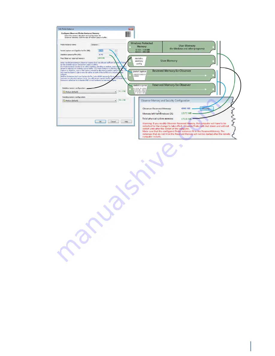
How a probe uses RAM

Chapter 14: Understanding How a Probe Uses RAM 309


Figure 143: How to resize various memory options


Packet capture buffer and statistics buffer

There are two kinds of buffers that a probe uses to store data in real-time:

capture buffers and statistical buffers. The capture buffer stores the raw data

captured from the network while the statistical buffer stores data entries that

are snapshots of a given statistical data point.
Selecting an appropriate capture buffer size given system resources is all most

users need to worry about; the default settings for the statistical buffers work

perfectly fine in the vast majority of circumstances.
However, if you are pushing the limits of your probe system by creating many

probe instances, you may be able to avoid some performance problems by fine-

tuning the memory allocation for each probe instance.
For example, suppose you want to give a number of remote administrators

access to Top Talkers data from a given probe. You will be able to add more probe

instances within a given system’s memory constraints if you set up the statistics

buffers to only allocate memory for tracking Top Talkers and to not allocate

memory for statistics that no one will be looking at.
Observer has no limitations on the amount of RAM that can be used for a buffer.
Note that when run on a 64-bit Windows, there is no 4 GB limitation for the

capture buffer; you are limited only by the amount of physical memory installed

on the probe.
In all cases, the actual buffer size (Max Buffer Size) is also reduced by 7% for

memory management purposes. Should you try and exceed the Max Buffer Size

an error dialog will be displayed indicating the minimum and maximum buffer

size for your Observer (or probe) buffer.
For passive probe instances, which are most often used for troubleshooting, the

default settings should be sufficient. If you are creating an active probe instance

(one that writes to disk and not just reads from it), then you may want to use the

following formula as a rough guideline to determine how much RAM to reserve

Summary of Contents for Apex Enterprise G3-APEX-ENT-32T

Page 1: ...Observer GigaStor 17 2 0 0 User Guide 23 Feb 2018 ...

Page 2: ...3 GS 2P40 288T 22 G3 GS 2P40 288T technical specifications 22 Parts list 24 G3 GS 2P40 288T installation 25 G3 GS 8P 1152T 28 G3 GS 8P 1152T technical specifications 28 Parts list 30 G3 GS 8P 1152T installation 30 G3 GS 8P 768T 33 G3 GS 8P 768T technical specifications 33 Parts list 34 G3 GS 8P 768T installation 35 G3 GS 8P 576T 37 G3 GS 8P 576T technical specifications 37 Parts list 39 G3 GS 8P 5...

Page 3: ...ion 65 G3 GS 4P 16T 67 G3 GS 4P 16T technical specifications 67 Parts list 68 G3 GS 4P 16T installation 69 G3 APEX ENT 32T 71 Apex technical specifications 71 Parts list 72 G3 APEX ENT 32T installation 72 VIAVI Rail Kit G3 GS Edition 73 How to attach the rails 74 How to install the system into your rack 76 How to remove the server from the rack 77 GS 2P40 576T 77 GS 2P40 576T technical specificati...

Page 4: ...llation 157 GSP 8P 9T 158 GSP 8P 9T technical specifications 158 About GSP 8P 9T 160 GSP 8P 9T installation 161 GSP 8P 6TSSD 162 GSP 8P 6TSSD technical specifications 162 About GSP 8P 6TSSD 163 GSP 8P 6TSSD installation 164 APEX ENT 32T 165 Apex technical specifications 165 Parts list 166 APEX ENT 32T installation 167 VIAVI Rail Kit Gen3 Edition 168 How to install the rails 168 How to remove your ...

Page 5: ... GigaStor 199 Defining your subnets in GigaStor 199 Tracking individual analysis ports 199 Configuring the packet capture and GigaStor buffer size 200 How to change the GigaStor storage directory or drive 200 Chapter 4 About Probe Instances 202 Introducing Probes 202 What is a probe instance 203 Which software probe is right for you 205 How probes work with switches 207 Chapter 5 Deploying Probes ...

Page 6: ...ic analysis 233 Importing Snort rules 234 Analyzing packets using Snort rules 234 Creating a Forensic Settings profile 235 Using network forensics to track a security breach 240 Using network forensics to track acceptable use or compliance 241 Chapter 10 Microbursts 242 Searching for microbursts 242 Using the Microburst Analysis tab in the GigaStor Control Panel 244 Using the Detail Chart only 244...

Page 7: ... How to delete RAID sets 273 How to build new RAID sets 275 How to stripe the volumes in Windows 276 How to disable the Recycle Bin for RAID 277 How to create folders for the RAID drives 277 GS 8P 192T 277 How to delete saved network data 278 How to reformat the RAID volume 278 How to delete RAID sets 279 How to build new RAID sets 280 How to stripe the volumes in Windows 281 How to disable the Re...

Page 8: ... volume 301 How to delete RAID sets 301 How to build new RAID sets 302 How to stripe the volumes in Windows 303 How to disable the Recycle Bin for RAID 304 How to create folders for the RAID drives 304 Understanding RAID array notifications 304 How to monitor the RAID drives through email notifications 305 Chapter 14 Understanding How a Probe Uses RAM 307 How a probe uses RAM 307 Packet capture bu...

Page 9: ... to remove duplicate packets from saved captures 350 Chapter 16 Troubleshooting 352 Troubleshooting common issues 352 Troubleshooting a slow probe system 353 A probe is not connecting to the analyzer or vice versa 353 No network adapter available 354 Integrated adapters report all sent packets with bad TCP checksum 355 No VLAN shown while using a Gigabit NIC 355 VLAN Statistics tool is not working...

Page 10: ...e range 362 Choppy data stream 362 CRC or TCP checksum errors wrong packet types 362 Packet capture does not start on Gen3 capture card 363 Chapter 17 Backups and Restoring 369 Backups and Restoring 369 Exporting GigaStor data for archiving 369 Backing up your GigaStor settings 370 How to restore a GigaStor probe to factory settings 371 Index 373 ...

Page 11: ...e technical specifications parts list and installation instructions For the newer G3 GS models see Observer Platform appliance installation G3 GS models G3 GS 2P40 1152T The G3 GS 2P40 1152T is best suited for 40 Gb data centers G3 GS 2P40 1152T technical specifications page 11 G3 GS 2P40 1152T technical specifications The technical specifications for the product are shown below ...

Page 12: ...t Figure 2 G3 GS 2P40 1152T Rear System Deployment 40 Gb data center Base storage 1 2 PB Max storage 1 2 PB Lights Out Management LOM Yes Redundant OS drive Yes OS drive hot swappable Yes OS drive size 1 TB RAID drive hot swappable Yes RAID version 50 Rail kit Yes Operating system Windows 2012 R2 Physical ...

Page 13: ... If applicable mounted weight includes any rail kits 2 SFP may be any of Copper 10 100 1000 1Gb SX LX SFP may be any of 10Gb SR LR QSPF may be any 40Gb SR LR BiDi Universal Parts list Each appliance comes packed in a number of boxes The boxes contain the various components necessary for a successful installation The boxes are not numbered as listed here The numbers merely represent how many boxes ...

Page 14: ...any maintenance 1 Take the appliance and all other components out of the packing materials 2 Attach the official rail kits page 73 to your server rack or cabinet 3 Install the head unit A1 into your server rack or cabinet Use a server lift if necessary Do not remove the RAID drives from the chassis 4 Install the JBOD unit s into your cabinet Use a server lift if necessary Do not remove the RAID dr...

Page 15: ...ect the analyzer port on the TAP to the SFP transceivers in the capture card d If you have more than one TAP to connect repeat the process for each TAP 11 Connect a monitor keyboard and mouse to the hardware appliance You can use a KVM switch if desired The KVM must be compatible with the operating system used on the appliance The user input devices or KVM switch are only temporarily needed to set...

Page 16: ...6 in the BIOS using a static IP address provided by your network administrator 17 Optional Change the JBOD IPMI port in the BIOS using a static IP address provided by your network administrator 18 Double click the Observer icon on the Desktop to start Observer Your hardware appliance is installed and on your network Next give the ETH0 IP address and IPMI port address if using to the Observer admin...

Page 17: ...G3 GS 2P40 576T Chapter 1 Appliance installation 17 Figure 5 G3 GS 2P40 576T Front Figure 6 G3 GS 2P40 576T Rear System Deployment 40 Gb data center Base storage 576 TB Max storage 1 2 PB ...

Page 18: ...cy 50 60Hz Input voltage 100V 240V Auto Select Operational current amps 19 7A BTU 7385 BTU hr Operational voltage 120V Power dissipation watts 2350W Relative humidity non condensing 5 85 Temperature operating 50 F 95 F 10 C 35 C Temperature storage 4 F 149 F 20 C 65 C 1 If applicable mounted weight includes any rail kits 2 SFP may be any of Copper 10 100 1000 1Gb SX LX SFP may be any of 10Gb SR LR...

Page 19: ...tallation Getting your appliance installed is the first step to greater visibility of your network This topic covers installing your appliance in the cabinet and connecting it to your network Caution Do not attempt in cabinet repairs of your appliance The appliance is very heavy Always use a server lift or work with a partner to install or remove the appliance from the cabinet to perform any maint...

Page 20: ...A Lights Out Management or IPMI port provides you a dedicated management channel for device maintenance It allows you to monitor start stop and manage your appliance remotely regardless of whether the appliance is powered on 8 Install SFP transceivers page 179 2 into the open slots on the back of the capture card s 9 If you are connecting to SPAN mirror ports of a network switch connect a straight...

Page 21: ...et 12 Turn on all JBOD unit s a Plug the power cords into the rear of the power supplies b Wait until the blue Information LED starts to blink c Use the tip of your finger to press the power button once The JBOD control board initiates the power up sequence in three seconds See Startup and shutdown G3 GS models page 172 Caution The RAID does not properly initialize if the JBOD unit s are not start...

Page 22: ...stalled and on your network Next give the ETH0 IP address and IPMI port address if using to the Observer administrator They need the addresses to add this GigaStor probe to Observer to capture network traffic with a probe instance G3 GS 2P40 288T The G3 GS 2P40 288T is best suited for 40 Gb data centers G3 GS 2P40 288T technical specifications page 22 G3 GS 2P40 288T technical specifications The t...

Page 23: ...23 Figure 10 G3 GS 2P40 288T Rear System Deployment 40 Gb data center Base storage 288 TB Max storage 1 2 PB Lights Out Management LOM Yes Redundant OS drive Yes OS drive hot swappable Yes OS drive size 1 TB RAID drive hot swappable Yes RAID version 5 ...

Page 24: ...ve humidity non condensing 5 85 Temperature operating 50 F 95 F 10 C 35 C Temperature storage 4 F 149 F 20 C 65 C 1 If applicable mounted weight includes any rail kits 2 SFP may be any of Copper 10 100 1000 1Gb SX LX SFP may be any of 10Gb SR LR QSPF may be any 40Gb SR LR BiDi Universal Parts list Each appliance comes packed in a number of boxes The boxes contain the various components necessary f...

Page 25: ...r visibility of your network This topic covers installing your appliance in the cabinet and connecting it to your network Caution Do not attempt in cabinet repairs of your appliance The appliance is very heavy Always use a server lift or work with a partner to install or remove the appliance from the cabinet to perform any maintenance 1 Take the appliance and all other components out of the packin...

Page 26: ...mote Desktop or other tools to control or configure Windows or Windows applications such as Observer 7 Optional Connect an Ethernet cable from your router or switch to the LOM or IPMI port Optional A Lights Out Management or IPMI port provides you a dedicated management channel for device maintenance It allows you to monitor start stop and manage your appliance remotely regardless of whether the a...

Page 27: ...an one TAP to connect repeat the process for each TAP 11 Connect a monitor keyboard and mouse to the hardware appliance You can use a KVM switch if desired The KVM must be compatible with the operating system used on the appliance The user input devices or KVM switch are only temporarily needed to set the IP address so you can disconnect them after the IP address is set 12 Turn on all JBOD unit s ...

Page 28: ...administrator 17 Optional Change the JBOD IPMI port in the BIOS using a static IP address provided by your network administrator 18 Double click the Observer icon on the Desktop to start Observer Your hardware appliance is installed and on your network Next give the ETH0 IP address and IPMI port address if using to the Observer administrator They need the addresses to add this GigaStor probe to Ob...

Page 29: ... RAID drive hot swappable Yes RAID version 50 Rail kit Yes Operating system Windows 2012 R2 Physical Height 48U 12 x 4U Width 19 in Depth 26 in Weight mounted 1 1216 lbs Weight handling 1276 6 lbs Media Monitoring interfaces 8 Speed 1 10 Gb Accepted transceivers 2 SFP SFP Performance Aggregate performance 40 Gbps Power Redundant power supply Yes Input frequency 50 60Hz Input voltage 100V 240V Auto...

Page 30: ...ation envelope containing the product license 1 Quick Start Guide 1 Label listing serial numbers of all JBODs for this system This label appears on top of the head unit and was attached to the outside of the head unit s box Use this label to sort and connect the proper JBODs to the head unit SFP transceivers if ordered For each JBOD 11 a box that contains 1 JBOD Unit with RAID drives preinstalled ...

Page 31: ... Windows Remote Desktop or other tools to control or configure Windows or Windows applications such as Observer 7 Optional Connect an Ethernet cable from your router or switch to the LOM or IPMI port Optional A Lights Out Management or IPMI port provides you a dedicated management channel for device maintenance It allows you to monitor start stop and manage your appliance remotely regardless of wh...

Page 32: ...ddress is set 12 Turn on all JBOD unit s a Plug the power cords into the rear of the power supplies b Wait until the blue Information LED starts to blink c Use the tip of your finger to press the power button once The JBOD control board initiates the power up sequence in three seconds See Startup and shutdown G3 GS models page 172 Caution The RAID does not properly initialize if the JBOD unit s ar...

Page 33: ...to the Observer administrator They need the addresses to add this GigaStor probe to Observer to capture network traffic with a probe instance G3 GS 8P 768T The G3 GS 8P 768T is best suited for 40 Gb data centers G3 GS 8P 768T technical specifications page 33 G3 GS 8P 768T technical specifications The technical specifications for the product are shown below Figure 17 G3 GS 8P 768T Front Figure 18 G...

Page 34: ...tional current amps 25 1A BTU 9377 BTU hr Operational voltage 120V Power dissipation watts 2985W Relative humidity non condensing 5 85 Temperature operating 50 F 95 F 10 C 35 C Temperature storage 4 F 149 F 20 C 65 C 1 If applicable mounted weight includes any rail kits 2 SFP may be any of Copper 10 100 1000 1Gb SX LX SFP may be any of 10Gb SR LR QSPF may be any 40Gb SR LR BiDi Universal Parts lis...

Page 35: ...abinet and connecting it to your network Caution Do not attempt in cabinet repairs of your appliance The appliance is very heavy Always use a server lift or work with a partner to install or remove the appliance from the cabinet to perform any maintenance 1 Take the appliance and all other components out of the packing materials 2 Attach the official rail kits page 73 to your server rack or cabine...

Page 36: ...port from your server firewall router or switch to the Link A port on the TAP b Connect the TX port from your other switch to the Link B port on the TAP c Use two analyzer cables to connect the analyzer port on the TAP to the SFP transceivers in the capture card d If you have more than one TAP to connect repeat the process for each TAP 11 Connect a monitor keyboard and mouse to the hardware applia...

Page 37: ...r environment 16 Optional Change the IPMI port page 176 in the BIOS using a static IP address provided by your network administrator 17 Optional Change the JBOD IPMI port in the BIOS using a static IP address provided by your network administrator 18 Double click the Observer icon on the Desktop to start Observer Your hardware appliance is installed and on your network Next give the ETH0 IP addres...

Page 38: ... GS 8P 576T 38 GigaStor 23 Feb 2018 Archive Non authoritative version Figure 21 G3 GS 8P 576T Front Figure 22 G3 GS 8P 576T Rear System Deployment 40 Gb data center Base storage 576 TB Max storage 1 2 PB ...

Page 39: ... Input voltage 100V 240V Auto Select Operational current amps 19 7A BTU 7385 BTU hr Operational voltage 120V Power dissipation watts 2350W Relative humidity non condensing 5 85 Temperature operating 50 F 95 F 10 C 35 C Temperature storage 4 F 149 F 20 C 65 C 1 If applicable mounted weight includes any rail kits 2 SFP may be any of Copper 10 100 1000 1Gb SX LX SFP may be any of 10Gb SR LR QSPF may ...

Page 40: ... 576T installation Getting your appliance installed is the first step to greater visibility of your network This topic covers installing your appliance in the cabinet and connecting it to your network Caution Do not attempt in cabinet repairs of your appliance The appliance is very heavy Always use a server lift or work with a partner to install or remove the appliance from the cabinet to perform ...

Page 41: ... Management or IPMI port provides you a dedicated management channel for device maintenance It allows you to monitor start stop and manage your appliance remotely regardless of whether the appliance is powered on 8 Install SFP transceivers page 179 6 into the open slots on the back of the capture card s 9 If you are connecting to SPAN mirror ports of a network switch connect a straight through Eth...

Page 42: ...ddress is set 12 Turn on all JBOD unit s a Plug the power cords into the rear of the power supplies b Wait until the blue Information LED starts to blink c Use the tip of your finger to press the power button once The JBOD control board initiates the power up sequence in three seconds See Startup and shutdown G3 GS models page 172 Caution The RAID does not properly initialize if the JBOD unit s ar...

Page 43: ...twork Next give the ETH0 IP address and IPMI port address if using to the Observer administrator They need the addresses to add this GigaStor probe to Observer to capture network traffic with a probe instance G3 GS 8P 384T The G3 GS 8P 384T is best suited for 40 Gb data centers G3 GS 8P 384T technical specifications page 43 G3 GS 8P 384T technical specifications The technical specifications for th...

Page 44: ... handling 436 6 lbs Media Monitoring interfaces 8 Speed 1 10 Gb Accepted transceivers 2 SFP SFP Performance Aggregate performance 40 Gbps Power Redundant power supply Yes Input frequency 50 60Hz Input voltage 100V 240V Auto Select Operational current amps 14 3A BTU 5391 BTU hr Operational voltage 120V Power dissipation watts 1716W Relative humidity non condensing 5 85 Temperature operating 50 F 95...

Page 45: ... Kit 2 Power supply cables Mini SAS cable s Before installing ensure you received all of the parts required for your system G3 GS 8P 384T installation Getting your appliance installed is the first step to greater visibility of your network This topic covers installing your appliance in the cabinet and connecting it to your network Caution Do not attempt in cabinet repairs of your appliance The app...

Page 46: ...provides you a dedicated management channel for device maintenance It allows you to monitor start stop and manage your appliance remotely regardless of whether the appliance is powered on 8 Install SFP transceivers page 179 7 into the open slots on the back of the capture card s 9 If you are connecting to SPAN mirror ports of a network switch connect a straight through Ethernet cable from the SPAN...

Page 47: ...ze if the JBOD unit s are not started first If this happens restart the head unit 13 Turn on the head unit A1 and wait for the RAID to initialize using the same procedure as the JBOD 14 In Windows change the IP address page 174 for the ETH0 port shown as ETH0 in Network Connections in Windows using information supplied to you by your network administrator The default IP address 192 168 1 10 is pri...

Page 48: ...G3 GS 8P 288T 48 GigaStor 23 Feb 2018 Archive Non authoritative version Figure 29 G3 GS 8P 288T Front ...

Page 49: ...49 Figure 30 G3 GS 8P 288T Rear System Deployment 40 Gb data center Base storage 288 TB Max storage 1 2 PB Lights Out Management LOM Yes Redundant OS drive Yes OS drive hot swappable Yes OS drive size 1 TB RAID drive hot swappable Yes RAID version 5 ...

Page 50: ...tive humidity non condensing 5 85 Temperature operating 50 F 95 F 10 C 35 C Temperature storage 4 F 149 F 20 C 65 C 1 If applicable mounted weight includes any rail kits 2 SFP may be any of Copper 10 100 1000 1Gb SX LX SFP may be any of 10Gb SR LR QSPF may be any 40Gb SR LR BiDi Universal Parts list Each appliance comes packed in a number of boxes The boxes contain the various components necessary...

Page 51: ...visibility of your network This topic covers installing your appliance in the cabinet and connecting it to your network Caution Do not attempt in cabinet repairs of your appliance The appliance is very heavy Always use a server lift or work with a partner to install or remove the appliance from the cabinet to perform any maintenance 1 Take the appliance and all other components out of the packing ...

Page 52: ...te Desktop or other tools to control or configure Windows or Windows applications such as Observer 7 Optional Connect an Ethernet cable from your router or switch to the LOM or IPMI port Optional A Lights Out Management or IPMI port provides you a dedicated management channel for device maintenance It allows you to monitor start stop and manage your appliance remotely regardless of whether the app...

Page 53: ...n one TAP to connect repeat the process for each TAP 11 Connect a monitor keyboard and mouse to the hardware appliance You can use a KVM switch if desired The KVM must be compatible with the operating system used on the appliance The user input devices or KVM switch are only temporarily needed to set the IP address so you can disconnect them after the IP address is set 12 Turn on all JBOD unit s a...

Page 54: ...dministrator 17 Optional Change the JBOD IPMI port in the BIOS using a static IP address provided by your network administrator 18 Double click the Observer icon on the Desktop to start Observer Your hardware appliance is installed and on your network Next give the ETH0 IP address and IPMI port address if using to the Observer administrator They need the addresses to add this GigaStor probe to Obs...

Page 55: ...torage 192 TB Max storage 768 TB Lights Out Management LOM Yes Redundant OS drive Yes OS drive hot swappable Yes OS drive size 1 TB RAID drive hot swappable Yes RAID version 5 Rail kit Yes Operating system Windows 2012 R2 Physical Height 8U 2 x 4U Width 19 in Depth 26 in Weight mounted 1 216 lbs Weight handling 226 6 lbs Media ...

Page 56: ... LR BiDi Universal Parts list Each appliance comes packed in a number of boxes The boxes contain the various components necessary for a successful installation The boxes are not numbered as listed here The numbers merely represent how many boxes you should expect and what is contained in each one Box 1 1 Head unit with RAID drives preinstalled 1 Rail kit 2 Power supply cables 2 Ethernet cables 1 P...

Page 57: ...Always use a server lift or work with a partner to install or remove the appliance from the cabinet to perform any maintenance 1 Take the appliance and all other components out of the packing materials 2 Attach the official rail kits page 73 to your server rack or cabinet 3 Install the head unit A1 into your server rack or cabinet Use a server lift if necessary Do not remove the RAID drives from t...

Page 58: ...e SPAN mirror ports on your switch to the SFP transceivers on the capture card 10 If you are connecting to a network TAP sold separately Figure 36 Connecting the TAP to the network device switch and analyzer a Connect the TX port from your server firewall router or switch to the Link A port on the TAP b Connect the TX port from your other switch to the Link B port on the TAP c Use two analyzer cab...

Page 59: ...inted on a sticker attached to the top of the appliance 15 Ensure the time zone settings match your environment 16 Optional Change the IPMI port page 176 in the BIOS using a static IP address provided by your network administrator 17 Optional Change the JBOD IPMI port in the BIOS using a static IP address provided by your network administrator 18 Double click the Observer icon on the Desktop to st...

Page 60: ...M Yes Redundant OS drive Yes OS drive hot swappable Yes OS drive size 1 TB RAID drive hot swappable Yes RAID version 5 Rail kit Yes Operating system Windows 2012 R2 Physical Height 4U Width 19 in Depth 26 in Weight mounted 1 116 lbs Weight handling 121 6 lbs Media Monitoring interfaces 8 Speed 1 10 Gb Accepted transceivers 2 SFP SFP Performance Aggregate performance 10 Gbps Power Redundant power s...

Page 61: ...ch one Box 1 1 Head unit with RAID drives preinstalled 1 Rail kit 2 Power supply cables 2 Ethernet cables 1 Product Activation Information envelope containing the product license 1 Quick Start Guide Before installing ensure you received all of the parts required for your system G3 GS 8P 96T installation Getting your appliance installed is the first step to greater visibility of your network This t...

Page 62: ...P transceivers in the capture card d If you have more than one TAP to connect repeat the process for each TAP 9 Connect a monitor keyboard and mouse to the hardware appliance You can use a KVM switch if desired The KVM must be compatible with the operating system used on the appliance The user input devices or KVM switch are only temporarily needed to set the IP address so you can disconnect them ...

Page 63: ...cal specifications for the product are shown below Figure 39 G3 GS 4P 32T Front Figure 40 G3 GS 4P 32T Rear System Deployment Medium data center Base storage 32 TB Max storage 32 TB Lights Out Management LOM Yes Redundant OS drive Yes OS drive hot swappable Yes OS drive size 1 TB RAID drive hot swappable Yes RAID version 5 Rail kit Yes Operating system Windows 2012 R2 Physical Height 2U Width 19 i...

Page 64: ...1 If applicable mounted weight includes any rail kits 2 SFP may be any of Copper 10 100 1000 1Gb SX LX SFP may be any of 10Gb SR LR QSPF may be any 40Gb SR LR BiDi Universal Parts list Each appliance comes packed in a number of boxes The boxes contain the various components necessary for a successful installation The boxes are not numbered as listed here The numbers merely represent how many boxes...

Page 65: ...chassis 4 Using an Ethernet cable connect the ETH0 port to the network Connecting the ETH0 port allows you to use Windows Remote Desktop or other tools to control or configure Windows or Windows applications such as Observer 5 Optional Connect an Ethernet cable from your router or switch to the LOM or IPMI port Optional A Lights Out Management or IPMI port provides you a dedicated management chann...

Page 66: ...itialize After plugging in the power cords wait until the blue Information LED starts to blink Press the power button once The power button is located on the front of the appliance The control board initiates the power up sequence in three seconds The entire process may take a couple of minutes 11 In Windows change the IP address page 174 for the ETH0 port shown as ETH0 in Network Connections in W...

Page 67: ...chnical specifications for the product are shown below Figure 42 G3 GS 4P 16T Front Figure 43 G3 GS 4P 16T Rear System Deployment Small data center or network edge Base storage 16 TB Max storage 16 TB Lights Out Management LOM Yes Redundant OS drive Yes OS drive hot swappable Yes OS drive size 1 TB RAID drive hot swappable Yes RAID version 5 Rail kit Yes Operating system Windows 2012 R2 Physical H...

Page 68: ...f applicable mounted weight includes any rail kits 2 SFP may be any of Copper 10 100 1000 1Gb SX LX SFP may be any of 10Gb SR LR QSPF may be any 40Gb SR LR BiDi Universal Parts list Each appliance comes packed in a number of boxes The boxes contain the various components necessary for a successful installation The boxes are not numbered as listed here The numbers merely represent how many boxes yo...

Page 69: ...chassis 4 Using an Ethernet cable connect the ETH0 port to the network Connecting the ETH0 port allows you to use Windows Remote Desktop or other tools to control or configure Windows or Windows applications such as Observer 5 Optional Connect an Ethernet cable from your router or switch to the LOM or IPMI port Optional A Lights Out Management or IPMI port provides you a dedicated management chann...

Page 70: ...itialize After plugging in the power cords wait until the blue Information LED starts to blink Press the power button once The power button is located on the front of the appliance The control board initiates the power up sequence in three seconds The entire process may take a couple of minutes 11 In Windows change the IP address page 174 for the ETH0 port shown as ETH0 in Network Connections in W...

Page 71: ...s Figure 45 G3 APEX ENT 32T Front Figure 46 G3 APEX ENT 32T Rear System Deployment Base storage 32 TB Max storage 32 TB Lights Out Management LOM Yes Redundant OS drive Yes OS drive hot swappable Yes OS drive size 1 TB RAID drive hot swappable Yes RAID version 5 Rail kit Model 22113260 Yes Operating system Windows 2012 R2 Physical Height 2U Width 19 in Depth 26 in Weight mounted 1 71 lbs ...

Page 72: ...ny of 10Gb SR LR QSPF may be any 40Gb SR LR BiDi Universal Parts list Each appliance comes packed in a number of boxes The boxes contain the various components necessary for a successful installation The boxes are not numbered as listed here The numbers merely represent how many boxes you should expect and what is contained in each one Box 1 1 Head unit with RAID drives preinstalled 1 Rail kit 2 P...

Page 73: ...ating system used on the appliance The user input devices or KVM switch are only temporarily needed to set the IP address so you can disconnect them after the IP address is set 7 Turn on the appliance and wait for the RAID to initialize After plugging in the power cords wait until the blue Information LED starts to blink Press the power button once The power button is located on the front of the a...

Page 74: ...include two sets of rail assemblies two rail mounting brackets mounting screws and washers to mount the system into the rack This rail will fit a rack between 26 5 and 36 4 deep 1 Identify the inner rack rails The chassis package includes one pair of rack rail assemblies in the rack mounting kit Each assembly consists of an inner rail that secures to the chassis and an outer rail that is attached ...

Page 75: ...he chassis 4 Optional If desired secure the rail with two flat head M4 x 4mm screws and washers as illustrated 5 Repeat for the other inner rail Figure 48 Installing the inner rails 6 Identify the outer rack rails 7 Press upward on the locking tab at the rear end of the middle rail 8 Push the middle rail back into the outer rail 9 Hang the hooks on the front of the outer rail onto the square holes...

Page 76: ...vides information on installing a chassis into a rack unit with the rails provided There are a variety of rack units on the market so the assembly procedure may differ slightly Also refer to the installation instructions for your rack unit Caution Do not pick up the server by the front handles They are designed to pull the system from a rack only 1 Align the chassis rails with the front of the rac...

Page 77: ...ver lift 1 Pull the chassis forward out the front of the rack until it stops 2 Press the release latches on each of the inner rails downward simultaneously and move the chassis forward in the rack Figure 50 Removing the server from the rack VIAVI page 73 Rail Kit G3 GS Edition page 73 GS 2P40 576T The GS 2P40 576T is best suited for 40 Gb data centers GS 2P40 576T technical specifications page 77 ...

Page 78: ...GS 2P40 576T 78 GigaStor 23 Feb 2018 Archive Non authoritative version Figure 51 GS 2P40 576T Front ...

Page 79: ... PB Lights Out Management LOM Yes Redundant OS drive Yes OS drive hot swappable Yes OS drive size 1 TB RAID drive hot swappable Yes RAID version 50 Rail kit Model 22113260 Yes Operating system Windows 2012 R2 Physical Height 30U 6 x 5U Width 19 in Depth 26 in Weight mounted 1 616 lbs Weight handling 80 lbs Media Monitoring interfaces 2 Speed 40 Gb ...

Page 80: ... 1000 1Gb SX LX SFP may be any of 10Gb SR LR QSPF may be any 40Gb SR LR BiDi Universal Parts list Each appliance comes packed in a number of boxes The boxes contain the various components necessary for a successful installation The boxes are not numbered as listed here The numbers merely represent how many boxes you should expect and what is contained in each one Box 1 1 Head unit 1 Rail kit 10 32...

Page 81: ... appliance The appliance is very heavy Always use a server lift or work with a partner to install or remove the appliance from the cabinet to perform any maintenance 1 Take the appliance and all other components out of the packing materials 2 Attach the official rail kits page 168 to your server rack or cabinet 3 Install the empty head unit A1 into your server rack or cabinet 4 Install the empty J...

Page 82: ...s such as Observer 9 Optional Connect an Ethernet cable from your router or switch to the LOM or IPMI port Optional A Lights Out Management or IPMI port provides you a dedicated management channel for device maintenance It allows you to monitor start stop and manage your appliance remotely regardless of whether the appliance is powered on 10 Install SFP transceivers page 179 13 into the open slots...

Page 83: ...e Startup and shutdown GS models page 171 Caution The RAID does not properly initialize if the JBOD unit s are not started first If this happens restart the head unit 15 Turn on the head unit A1 and wait for the RAID to initialize 16 In Windows change the IP address page 174 for the 10 100 1000 port shown as OnBoard LAN 2 in Network Connections in Windows using information supplied to you by your ...

Page 84: ...ive Non authoritative version GS 2P40 288T The GS 2P40 288T is best suited for 40 Gb data centers GS 2P40 288T technical specifications page 84 GS 2P40 288T technical specifications The technical specifications for the product are shown below ...

Page 85: ...GS 2P40 288T Chapter 1 Appliance installation 85 Figure 55 GS 2P40 288T Front ...

Page 86: ...GS 2P40 288T 86 GigaStor 23 Feb 2018 Archive Non authoritative version Figure 56 GS 2P40 288T Rear System ...

Page 87: ...g 80 lbs Media Monitoring interfaces 2 Speed 40 Gb Accepted transceivers 2 QSFP Performance Aggregate performance 40 Gbps Power Redundant power supply Yes Input frequency 50 60Hz Input voltage 100V 240V Auto Select Operational current amps 11 60A BTU 4395 BTU hr Operational voltage 120V Power dissipation watts 1399W Relative humidity non condensing 20 80 Temperature operating 50 F 95 F 10 C 35 C T...

Page 88: ...duct license 1 Quick Start Guide SFP transceivers if ordered Box 2 24 RAID drives labeled A1 1 A1 24 TAP media kit s if ordered For each JBOD 2 a box that contains 1 JBOD Unit 1 Rail Kit 2 Power supply cables Mini SAS cable s A box that contains the RAID drives for each JBOD 2 24 RAID drives labeled B1 1 B1 24 24 RAID drives labeled C1 1 C1 24 Before installing ensure you received all of the parts...

Page 89: ...it A1 into your server rack or cabinet 4 Install the empty JBOD unit s into your cabinet Use a server lift if necessary Do not remove the RAID drives from the chassis Do not connect the power cables yet 5 Using the SAS cables connect the RAID ports from the JBOD unit s to the head unit Close inspection of the RAID ports on the JBOD unit s show two ports labeled OUT and one port labeled IN All port...

Page 90: ...GS 2P40 288T 90 GigaStor 23 Feb 2018 Archive Non authoritative version Figure 57 GS 2P40 288T Rear ...

Page 91: ...onitor start stop and manage your appliance remotely regardless of whether the appliance is powered on 10 Install SFP transceivers page 179 14 into the open slots on the back of the capture card s 11 If you are connecting to SPAN mirror ports of a network switch connect a straight through Ethernet cable from the SPAN mirror ports on your switch to the SFP transceivers on the capture card 12 If you...

Page 92: ... as OnBoard LAN 2 in Network Connections in Windows using information supplied to you by your network administrator The default IP address 192 168 1 10 is printed on a sticker attached to the top of the appliance 17 Ensure the time zone settings match your environment 18 Optional Change the LOM port page 176 in the BIOS using a static IP address provided by your network administrator 19 Double cli...

Page 93: ...GS 8P 576T Chapter 1 Appliance installation 93 Figure 59 GS 8P 576T Front ...

Page 94: ...rage 1 2 PB Lights Out Management LOM Yes Redundant OS drive Yes OS drive hot swappable Yes OS drive size 1 TB RAID drive hot swappable Yes RAID version 50 Rail kit Model 22113260 Yes Operating system Windows 2012 R2 Physical Height 30U 6 x 5U Width 19 in Depth 26 in Weight mounted 1 616 lbs Weight handling 80 lbs Media Monitoring interfaces 8 Speed 1 10 Gb ...

Page 95: ...SX LX SFP may be any of 10Gb SR LR QSPF may be any 40Gb SR LR BiDi Universal Parts list Each appliance comes packed in a number of boxes The boxes contain the various components necessary for a successful installation The boxes are not numbered as listed here The numbers merely represent how many boxes you should expect and what is contained in each one Box 1 1 Head unit 1 Rail kit 10 32 screws 4 ...

Page 96: ...s of your appliance The appliance is very heavy Always use a server lift or work with a partner to install or remove the appliance from the cabinet to perform any maintenance 1 Take the appliance and all other components out of the packing materials 2 Attach the official rail kits page 168 to your server rack or cabinet 3 Install the empty head unit A1 into your server rack or cabinet 4 Install th...

Page 97: ...erver 9 Optional Connect an Ethernet cable from your router or switch to the LOM or IPMI port Optional A Lights Out Management or IPMI port provides you a dedicated management channel for device maintenance It allows you to monitor start stop and manage your appliance remotely regardless of whether the appliance is powered on 10 Install SFP transceivers page 179 15 into the open slots on the back ...

Page 98: ... unit s See Startup and shutdown GS models page 171 Caution The RAID does not properly initialize if the JBOD unit s are not started first If this happens restart the head unit 15 Turn on the head unit A1 and wait for the RAID to initialize 16 In Windows change the IP address page 174 for the 10 100 1000 port shown as OnBoard LAN 2 in Network Connections in Windows using information supplied to yo...

Page 99: ...88T is best suited for 40 Gb data centers GS 8P 288T technical specifications page 99 Parts list page 122 GS 8P 288T page 123 installation page 123 GS 8P 288T technical specifications The technical specifications for the product are shown below Figure 63 GS 8P 288T Front ...

Page 100: ...GS 8P 288T 100 GigaStor 23 Feb 2018 Archive Non authoritative version ...

Page 101: ...GS 8P 288T Chapter 1 Appliance installation 101 ...

Page 102: ...GS 8P 288T 102 GigaStor 23 Feb 2018 Archive Non authoritative version ...

Page 103: ...GS 8P 288T Chapter 1 Appliance installation 103 ...

Page 104: ...GS 8P 288T 104 GigaStor 23 Feb 2018 Archive Non authoritative version ...

Page 105: ...GS 8P 288T Chapter 1 Appliance installation 105 ...

Page 106: ...GS 8P 288T 106 GigaStor 23 Feb 2018 Archive Non authoritative version ...

Page 107: ...GS 8P 288T Chapter 1 Appliance installation 107 ...

Page 108: ...GS 8P 288T 108 GigaStor 23 Feb 2018 Archive Non authoritative version ...

Page 109: ...GS 8P 288T Chapter 1 Appliance installation 109 ...

Page 110: ...GS 8P 288T 110 GigaStor 23 Feb 2018 Archive Non authoritative version ...

Page 111: ...GS 8P 288T Chapter 1 Appliance installation 111 Figure 64 GS 8P 288T Rear ...

Page 112: ...GS 8P 288T 112 GigaStor 23 Feb 2018 Archive Non authoritative version ...

Page 113: ...GS 8P 288T Chapter 1 Appliance installation 113 ...

Page 114: ...GS 8P 288T 114 GigaStor 23 Feb 2018 Archive Non authoritative version ...

Page 115: ...GS 8P 288T Chapter 1 Appliance installation 115 ...

Page 116: ...GS 8P 288T 116 GigaStor 23 Feb 2018 Archive Non authoritative version ...

Page 117: ...GS 8P 288T Chapter 1 Appliance installation 117 ...

Page 118: ...GS 8P 288T 118 GigaStor 23 Feb 2018 Archive Non authoritative version ...

Page 119: ...GS 8P 288T Chapter 1 Appliance installation 119 ...

Page 120: ...GS 8P 288T 120 GigaStor 23 Feb 2018 Archive Non authoritative version ...

Page 121: ... TB Max storage 1 2 PB Lights Out Management LOM Yes Redundant OS drive Yes OS drive hot swappable Yes OS drive size 1 TB RAID drive hot swappable Yes RAID version 5 Rail kit Model 22113260 Yes Operating system Windows 2012 R2 Physical Height 15U 3 x 5U Width 19 in Depth 26 in Weight mounted 1 316 lbs ...

Page 122: ...1 If applicable mounted weight includes any rail kits 2 SFP may be any of Copper 10 100 1000 1Gb SX LX SFP may be any of 10Gb SR LR QSPF may be any 40Gb SR LR BiDi Universal Parts list Each appliance comes packed in a number of boxes The boxes contain the various components necessary for a successful installation The boxes are not numbered as listed here The numbers merely represent how many boxes...

Page 123: ...pairs of your appliance The appliance is very heavy Always use a server lift or work with a partner to install or remove the appliance from the cabinet to perform any maintenance 1 Take the appliance and all other components out of the packing materials 2 Attach the official rail kits page 168 to your server rack or cabinet 3 Install the empty head unit A1 into your server rack or cabinet 4 Instal...

Page 124: ...GS 8P 288T 124 GigaStor 23 Feb 2018 Archive Non authoritative version Figure 65 GS 8P 288T Rear ...

Page 125: ...GS 8P 288T Chapter 1 Appliance installation 125 ...

Page 126: ...GS 8P 288T 126 GigaStor 23 Feb 2018 Archive Non authoritative version ...

Page 127: ...GS 8P 288T Chapter 1 Appliance installation 127 ...

Page 128: ...GS 8P 288T 128 GigaStor 23 Feb 2018 Archive Non authoritative version ...

Page 129: ...GS 8P 288T Chapter 1 Appliance installation 129 ...

Page 130: ...GS 8P 288T 130 GigaStor 23 Feb 2018 Archive Non authoritative version ...

Page 131: ...GS 8P 288T Chapter 1 Appliance installation 131 ...

Page 132: ...GS 8P 288T 132 GigaStor 23 Feb 2018 Archive Non authoritative version ...

Page 133: ...GS 8P 288T Chapter 1 Appliance installation 133 ...

Page 134: ... allows you to use Windows Remote Desktop or other tools to control or configure Windows or Windows applications such as Observer 9 Optional Connect an Ethernet cable from your router or switch to the LOM or IPMI port Optional A Lights Out Management or IPMI port provides you a dedicated management channel for device maintenance It allows you to monitor start stop and manage your appliance remotel...

Page 135: ... if desired The KVM must be compatible with the operating system used on the appliance The user input devices or KVM switch are only temporarily needed to set the IP address so you can disconnect them after the IP address is set 14 Turn on all JBOD unit s See Startup and shutdown GS models page 171 Caution The RAID does not properly initialize if the JBOD unit s are not started first If this happe...

Page 136: ...ort address if using to the Observer administrator They need the addresses to add this GigaStor probe to Observer to capture network traffic with a probe instance GS 8P 192T The GS 8P 192T is best suited for multi 10 Gb data centers GS 8P 192T technical specifications page 136 GS 8P 192T technical specifications The technical specifications for the product are shown below ...

Page 137: ...GS 8P 192T Chapter 1 Appliance installation 137 Figure 67 GS 8P 192T Front ...

Page 138: ...T Rear System Deployment Multi 10 Gb data center Base storage 192 TB Max storage 768 TB Lights Out Management LOM Yes Redundant OS drive Yes OS drive hot swappable Yes OS drive size 1 TB RAID drive hot swappable Yes RAID version 5 Rail kit Model 22113260 Yes Operating system Windows 2012 R2 ...

Page 139: ...y non condensing 20 80 Temperature operating 50 F 95 F 10 C 35 C Temperature storage 4 F 149 F 20 C 65 C 1 If applicable mounted weight includes any rail kits 2 SFP may be any of Copper 10 100 1000 1Gb SX LX SFP may be any of 10Gb SR LR QSPF may be any 40Gb SR LR BiDi Universal Parts list Each appliance comes packed in a number of boxes The boxes contain the various components necessary for a succ...

Page 140: ...et and connecting it to your network Caution Do not attempt in cabinet repairs of your appliance The appliance is very heavy Always use a server lift or work with a partner to install or remove the appliance from the cabinet to perform any maintenance 1 Take the appliance and all other components out of the packing materials 2 Attach the official rail kits page 168 to your server rack or cabinet 3...

Page 141: ... connect the 10 100 1000 port to the network Connecting the 10 100 1000 port allows you to use Windows Remote Desktop or other tools to control or configure Windows or Windows applications such as Observer 9 Optional Connect an Ethernet cable from your router or switch to the LOM or IPMI port Optional A Lights Out Management or IPMI port provides you a dedicated management channel for device maint...

Page 142: ...t repeat the process for each TAP 13 Connect a monitor keyboard and mouse to the hardware appliance You can use a KVM switch if desired The KVM must be compatible with the operating system used on the appliance The user input devices or KVM switch are only temporarily needed to set the IP address so you can disconnect them after the IP address is set 14 Turn on all JBOD unit s See Startup and shut...

Page 143: ... and on your network Next give the 10 100 1000 IP address and LOM port address if using to the Observer administrator They need the addresses to add this GigaStor probe to Observer to capture network traffic with a probe instance GS 8P 96T The GS 8P 96T is best suited for 1 Gb 10 Gb hybrid data centers GS 8P 96T technical specifications page 143 GS 8P 96T technical specifications The technical spe...

Page 144: ...ement LOM Yes Redundant OS drive Yes OS drive hot swappable Yes OS drive size 1 TB RAID drive hot swappable Yes RAID version 5 Rail kit Model 22113260 Yes Operating system Windows 2012 R2 Physical Height 5U Width 19 in Depth 26 in Weight mounted 1 116 lbs Weight handling 80 lbs Media Monitoring interfaces 8 Speed 1 10 Gb Accepted transceivers 2 SFP SFP Performance Aggregate performance 10 Gbps ...

Page 145: ...ontain the various components necessary for a successful installation The boxes are not numbered as listed here The numbers merely represent how many boxes you should expect and what is contained in each one Box 1 1 Head unit 1 Rail kit 10 32 screws 4 6mm screws 4 Rails 2 2 Power supply cables 1 Ethernet cable 2 keys for lock 1 USB drive containing restore image 1 Product Activation Information en...

Page 146: ...emote Desktop or other tools to control or configure Windows or Windows applications such as Observer 6 Optional Connect an Ethernet cable from your router or switch to the LOM or IPMI port Optional A Lights Out Management or IPMI port provides you a dedicated management channel for device maintenance It allows you to monitor start stop and manage your appliance remotely regardless of whether the ...

Page 147: ...t only blinks when there is activity for that specific RAID drive 12 In Windows change the IP address page 174 for the 10 100 1000 port shown as OnBoard LAN 2 in Network Connections in Windows using information supplied to you by your network administrator The default IP address 192 168 1 10 is printed on a sticker attached to the top of the appliance 13 Ensure the time zone settings match your en...

Page 148: ...ize 1 TB RAID drive hot swappable Yes RAID version 5 Rail kit Model 22113260 Yes Operating system Windows 2012 R2 Physical Height 2U Width 19 in Depth 26 in Weight mounted 1 71 lbs Weight handling 64 lbs Media Monitoring interfaces 4 Speed 1 10 Gb Accepted transceivers 2 SFP SFP Performance Aggregate performance 6 Gbps Power Redundant power supply Yes Input frequency 50 60Hz Input voltage 100V 240...

Page 149: ...1 Rail kit 10 32 screws 4 6mm screws 4 Rails 2 2 Power supply cables 1 Ethernet cable 2 keys for lock 1 USB drive containing restore image 1 Product Activation Information envelope containing the product license 1 Quick Start Guide SFP transceivers if ordered Box 2 8 RAID drives labeled A1 A8 TAP media kit s if ordered Before installing ensure you received all of the parts required for your system...

Page 150: ...nnel for device maintenance It allows you to monitor start stop and manage your appliance remotely regardless of whether the appliance is powered on 7 Install SFP transceivers page 179 19 into the open slots on the back of the capture card s 8 If you are connecting to SPAN mirror ports of a network switch connect a straight through Ethernet cable from the SPAN mirror ports on your switch to the SF...

Page 151: ... as OnBoard LAN 2 in Network Connections in Windows using information supplied to you by your network administrator The default IP address 192 168 1 10 is printed on a sticker attached to the top of the appliance 13 Ensure the time zone settings match your environment 14 Optional Change the LOM port page 176 in the BIOS using a static IP address provided by your network administrator 15 Double cli...

Page 152: ... OS drive size 1 TB RAID drive hot swappable Yes RAID version 5 Rail kit Model 22113260 Yes Operating system Windows 2012 R2 Physical Height 2U Width 19 in Depth 26 in Weight mounted 1 71 lbs Weight handling 64 lbs Media Monitoring interfaces 4 Speed 1 Gb Accepted transceivers 2 SFP Performance Aggregate performance 4 Gbps Power Redundant power supply Yes Input frequency 50 60Hz Input voltage 100V...

Page 153: ...1 Rail kit 10 32 screws 4 6mm screws 4 Rails 2 2 Power supply cables 1 Ethernet cable 2 keys for lock 1 USB drive containing restore image 1 Product Activation Information envelope containing the product license 1 Quick Start Guide SFP transceivers if ordered Box 2 8 RAID drives labeled A1 A8 TAP media kit s if ordered Before installing ensure you received all of the parts required for your system...

Page 154: ...nnel for device maintenance It allows you to monitor start stop and manage your appliance remotely regardless of whether the appliance is powered on 7 Install SFP transceivers page 179 20 into the open slots on the back of the capture card s 8 If you are connecting to SPAN mirror ports of a network switch connect a straight through Ethernet cable from the SPAN mirror ports on your switch to the SF...

Page 155: ...t shown as OnBoard LAN 2 in Network Connections in Windows using information supplied to you by your network administrator The default IP address 192 168 1 10 is printed on a sticker attached to the top of the appliance 13 Ensure the time zone settings match your environment 14 Optional Change the LOM port page 176 in the BIOS using a static IP address provided by your network administrator 15 Dou...

Page 156: ...ing 56 lbs Media Monitoring interfaces 8 Speed 1 10 Gb Accepted transceivers 2 SFP SFP Performance Aggregate performance 10 Gbps Power Redundant power supply Yes Input frequency 50 60Hz Input voltage 100V 240V Auto Select Operational current amps 2 10A BTU 792 BTU hr Operational voltage 120V Power dissipation watts 232W Relative humidity non condensing 20 80 Temperature operating 50 F 95 F 10 C 35...

Page 157: ...tart Guide Before installing ensure you received all of the parts required for your system GPA 8P installation Getting your appliance installed is the first step to greater visibility of your network This topic covers installing your appliance in the cabinet and connecting it to your network 1 Take the appliance and all other components out of the packing materials 2 Install SFP transceivers page ...

Page 158: ... analyzer port on the TAP to the SFP transceivers in the capture card d If you have more than one TAP to connect repeat the process for each TAP 5 Ensure the time zone settings match your environment 6 Double click the Observer icon on the Desktop to start Observer Your hardware appliance is installed and on your network GSP 8P 9T The GSP 8P 9T is best suited for any location GSP 8P 9T technical s...

Page 159: ... swappable No OS drive size 1 TB RAID drive hot swappable Yes RAID version 5 Rail kit Model 22113260 Operating system Windows 2012 R2 Physical Height 12 80 in Width 16 in Depth 8 in Weight mounted 1 29 lbs Weight handling 52 lbs Media Monitoring interfaces 8 Speed 1 10 Gb Accepted transceivers 2 SFP SFP Performance Aggregate performance 5 Gbps Power Redundant power supply No Input frequency 50 60H...

Page 160: ...e analyzer is a convenient way to monitor numerous locations on your network without permanently installing hardware thereby giving you the flexibility to troubleshoot issues where they occur With Portable Analyzer Systems Troubleshoot intermittent performance issues Obtain an independent look at data flow Gain real time metrics Perform retrospective network analysis Each System Includes Observer ...

Page 161: ...nto the open slots on the back of the capture card s 4 If you are connecting to SPAN mirror ports of a network switch connect a straight through Ethernet cable from the SPAN mirror ports on your switch to the SFP transceivers on the capture card 5 If you are connecting to a network TAP sold separately a Connect the TX port from your server firewall router or switch to the Link A port on the TAP b ...

Page 162: ... network GSP 8P 6TSSD The GSP 8P 6TSSD is best suited for any location GSP 8P 6TSSD technical specifications page 162 GSP 8P 6TSSD technical specifications The technical specifications for the product are shown below Figure 85 GSP 8P 6TSSD Front System Deployment Anywhere Base storage 6 TB Max storage 6 TB Lights Out Management LOM Yes Redundant OS drive No OS drive hot swappable No OS drive size ...

Page 163: ... LX SFP may be any of 10Gb SR LR QSPF may be any 40Gb SR LR BiDi Universal About GSP 8P 6TSSD A portable analyzer is a convenient way to monitor numerous locations on your network without permanently installing hardware thereby giving you the flexibility to troubleshoot issues where they occur With Portable Analyzer Systems Troubleshoot intermittent performance issues Obtain an independent look at...

Page 164: ... page 179 23 into the open slots on the back of the capture card s 4 If you are connecting to SPAN mirror ports of a network switch connect a straight through Ethernet cable from the SPAN mirror ports on your switch to the SFP transceivers on the capture card 5 If you are connecting to a network TAP sold separately a Connect the TX port from your server firewall router or switch to the Link A port...

Page 165: ...lled and on your network APEX ENT 32T The APEX ENT 32T is best suited for any data center Apex technical specifications The technical specifications for the product are shown below Figure 87 APEX ENT 32T Front Figure 88 APEX ENT 32T Rear System Deployment Base storage 32 TB Max storage 32 TB Lights Out Management LOM Yes Redundant OS drive Yes OS drive hot swappable Yes OS drive size 1 TB RAID dri...

Page 166: ... operating 50 F 95 F 10 C 35 C Temperature storage 4 F 149 F 20 C 65 C 1 If applicable mounted weight includes any rail kits 2 SFP may be any of Copper 10 100 1000 1Gb SX LX SFP may be any of 10Gb SR LR QSPF may be any 40Gb SR LR BiDi Universal Parts list Each appliance comes packed in a number of boxes The boxes contain the various components necessary for a successful installation The boxes are ...

Page 167: ...in a very specific location 5 Using an Ethernet cable connect the 10 100 1000 port to the network Connecting the 10 100 1000 port allows you to use Windows Remote Desktop or other tools to control or configure Windows or Windows applications such as Observer 6 Optional Connect an Ethernet cable from your router or switch to the LOM or IPMI port Optional A Lights Out Management or IPMI port provide...

Page 168: ...en3 Edition The VIAVI rail kit is used with its 2U and 5U 19 inch rack mounted appliances in four post L bracket or U bracket cabinets How to install the rails How to remove your appliance from the rails page 170 How to remove the rails from a cabinet page 170 Rail kit hardware page 171 How to install the rails Installation is fast and easy and no tools are required to install the rails in your ca...

Page 169: ...rails should slide easily to expand If it does not loosen the thumb screws 4 Insert the rear locking pins into your cabinet and pull towards you until the rail lock clicks into place Due to noise in your server room you may not hear it click Also the rail lock is small and you may not feel it catch Figure 90 Rear rail lock To test that the rail is locked into place gently push the rail away from y...

Page 170: ...oming out of the rack if pulled too hard Caution Appliances are very heavy Work with a partner and use extreme care when removing Because of the weight of the appliance we recommend that the appliance be fully removed from the cabinet for all maintenance 1 Pull the appliance toward you until it stops 2 On both sides of the appliance press the slide locks on the white plastic on the appliance and p...

Page 171: ...ctures its rails using high grade heavy duty materials These components comprise the rail kit The purple faced GigaStor contains these items The plastic slides were attached at the factory 10 32 screws 4 6mm screws 4 Rails 2 The blue faced GigaStor contains the above plus Plastic slides 2 Screws 10 VIAVI page 168 Rail Kit Gen3 Edition page 168 Startup and shutdown GS models Start Turn on all JBOD ...

Page 172: ...dels page 172 After a power loss The system will power up automatically approximately fifteen seconds after the power returns Startup and shutdown G3 GS models page 172 Power down Turn off the unit using a clean operating system shutdown from Windows 1 Turn off the head unit using a clean operating system shutdown before the JBOD unit s Always wait for the head unit to power off before turning off...

Page 173: ...liding the drive into place until the tabs can engage the slots on both sides of the drive Do not use force Slightly lift the drive tabs to ease insertion Figure 94 RAID drive 4 Repeat until all of the drives are installed as labeled You should push each drive slightly to ensure that it is fully seated Additionally you may want to visually inspect all of the drives from the side to verify that the...

Page 174: ...he circuit board assembly Never cover the small hole on top of the hard drive Never place the hard drive near equipment that produces strong magnetic fields Avoid moving any hard drive that is turned on and operating Avoid exposing the hard drive to extreme changes in temperature to minimize the risk of condensation If the temperature difference between the storage location and installation locati...

Page 175: ...the Properties dialog for that network connection Starting now all of your interaction with the hardware appliance can now be done remotely by connecting to the appliance using other Observer Platform products or Windows Remote Desktop depending on what you want to accomplish How to set the IP address GS models Set the IP address of the hardware appliance while you still have physical access to it...

Page 176: ...bled by default 4 Select Internet Protocol Version 4 TCP IPv4 and click Properties 5 Set the IP address subnet mask router or gateway and DNS server for your environment and click OK Figure 96 Default TCP IP settings 6 Click OK again to close the Properties dialog for that network connection Starting now all of your interaction with the hardware appliance can now be done remotely by connecting to ...

Page 177: ...BIOS Then you should change the administrator password to something different than the default 1 Connect an Ethernet cable from your router or switch to the IPMI or LOM port 2 When starting your appliance press Delete during POST to enter the BIOS setup 3 In the BIOS choose IPMI BMC network configuration Figure 97 BIOS IPMI tab 4 Set Update IPMI LAN configuration to Yes 5 Set Configuration Address...

Page 178: ...configured in step 6 The user name and password boxes are always case sensitive 9 Choose Configuration Users and select the second user account ADMIN account 10 Click Modify User and change the password 11 Optional Set up alerts G3 GS models only There is no audible alarm if there is an issue with a power supply unit Other alerting options are available Each must be configured separately using det...

Page 179: ... them or other components Avoid exposure to laser radiation from optical components by keeping the dust plugs installed until you are ready to install the cables There are numbers etched into the back plate of each Gen3 capture card along the top Figure 99 page 180 These etched numbers represent the port number assignments from top to bottom For example port 1 is at the top and port 4 at the botto...

Page 180: ...an be inserted into any open port and in any order You can hot swap the connected transceivers at any time but it is recommended you then re launch Observer so that the new speeds can be identified Figure 99 8 port 1 10 Gb 5U capture card port assignments Figure 100 2 port 40 Gb 5U capture card port assignments ...

Page 181: ...How to install the SFPs Chapter 1 Appliance installation 181 Figure 101 2U capture card port assignments ...

Page 182: ... probe as discussed in Deciding where to place probes in your network page 210 2 The GigaStor probe has been installed into a server rack It is important to install the RAID drives into the correct slots Ensure that monitoring interfaces are connected to the appropriate data feeds SPAN or mirror ports TAPs aggregation devices Ensure the configuration of these third party devices is done properly s...

Page 183: ...step 1 renaming the probe instance is different For details see Creating a probe instance Pay attention to the special instructions if your GigaStor array is larger than 256 TB 4 Set the adapter speed for the active instance See Configuring the probe s adapter speed ToS QoS precedence and statistics sampling 5 To capture network traffic you must have the GigaStor capture running See Configuring pr...

Page 184: ... any connection established after Expert Analysis was started If the conversation started before Expert Analysis was started Observer cannot see it By following the steps you successfully configured the GigaStor probe to collect network traffic You also made some configuration changes that help the GigaStor probe work well in your network Also you mined data from the GigaStor probe What is the Gig...

Page 185: ...tion X Physical Port Indexing X Precision Time Stamping X Virtual Adapters X High performance RAID card X Minimum and recommended system specifications If you are installing the software on your own hardware or a virtual machine these are the minimum and recommended specifications for a production environment Table 1 Observer Expert Console Only ECO Minimum Recommended Processor CPU Dual core Pent...

Page 186: ...for Observer This is a limitation of Windows known as the BIOS memory hole Either add more RAM or take some out 2 See for a full list of supported operating systems 3 A second network card that acts solely as a capture card is required and must be in promiscuous mode Alternatively a dual port NIC can be used Current compatibility and incompatibly of virtual machines with the GigaStor Software Edit...

Page 187: ...e trending data and your storage requirements for network trending data the network trending data could fill that drive to full capacity this is a problem Therefore determine your typical 24 hour data rate and how many days of trending data you want to retain The result indicates how much storage space is required To determine the amount of space required to store your desired amount of trending d...

Page 188: ...packets you want to include Use the sliders at the top of the time line chart to select the time period you are interested in analyzing then click Update Chart and Update Reports to update everything to the new time frame Right click in the top chart to open additional controls Figure 103 GigaStor Control Panel Summary tab If desired you can further constrain the display of packets by MAC Stations...

Page 189: ... the Observer User Guide TCP UDP Server applications By defining specific applications Observer can provide more detailed reports to you Observer has many applications already defined but you can add more if you wish See the Discovery section in the Observer User Guide The default settings for Observer is to not be aware of TCP connections that were opened after the GigaStor or packet capture star...

Page 190: ...or configuration options Capture Buffer size Only available if you are configuring an active GigaStor instance Allows you to set the amount of Windows memory that Observer will set aside to store captured packets Observer will show the buffer percentage full and give you an idea of what the best buffer size is for a particular situation You will want to capture an event in as little time with as l...

Page 191: ...IP Addresses TCP Applications UDP Applications VLANs MPLS Physical Ports and Network Packet Broker NPB Port Tagging These options are for controlling statistical display only All packets that the GigaStor sees are written to disk and is available for analyzing using the Analyze button The value configured in these boxes determine the maximum number of stations that are indexed by the GigaStor and ...

Page 192: ...s you need without burdening the system by analyzing every packet For even more details see Differences between statistics and packets page 215 Use physical port selections You can choose this option to display statistics sorted by capture card physical port This is useful when you want to troubleshoot the individual links without having to load the capture buffer by clicking Analyze If selected y...

Page 193: ...ers The solution is to shorten your time slice perhaps down to milliseconds if necessary so that the Top Talker list does not reach the 1000 stations Additionally you can increase the number of IP Addresses allowed in the list up to a maximum of 200 000 Also keep in mind that in the GigaStor Control Panel you are looking at statistics not actual packet data Therefore you could set the GigaStor Con...

Page 194: ...nformation about what these settings affect see Differences between statistics and packets page 215 and Understanding GigaStor indexing page 216 Hardening your GigaStor Based on your organization s requirements in addition to the default security settings you may need to change various options on the GigaStor especially for the operating system This is sometimes called hardening the system We reco...

Page 195: ...You should apply those updates as soon as feasible however you should always apply the updates manually We do not recommend that you allow Windows to automatically install the updates and restart the system By manually applying the updates you ensure that the system restarts properly and that the probe starts correctly whether running as a Windows service or as an application For your anti virus s...

Page 196: ... The management adapter is used to get the GigaStor onto your network by giving the appliance an IP address The management card is not the capture card 4 On Networking select Internet Protocol Version 4 TCP IPv4 and choose Properties The Internet Protocol Version 4 TCP IPv4 window opens on the General tab 5 Click Advanced The Advanced TCP IP Settings window opens 6 Click WINS and choose Disable Ne...

Page 197: ...background but are not generally needed for your GigaStor You may disable the features you deem unnecessary Most Windows features are not needed to read or write data to the RAID drives 1 In Windows Control Panel choose Programs and Features 2 On the left choose Turn Windows features on or off Figure 106 Programs and Features 3 Clear any feature you do not want to use You must keep Internet Explor...

Page 198: ...Hardening your GigaStor 198 GigaStor 23 Feb 2018 Archive Non authoritative version Figure 107 Windows Features Only the Windows features you want to use are remain ...

Page 199: ... that subnet information to its index files All future data analyzed will have subnet filtering readily available as well as statistical data On the IP Stations tab you see your subnets and you can perform statistical analysis based on subnets When you analyze data from captures with index files without any subnets defined there will be no subnet available in the IP stations tab even if the analyz...

Page 200: ...Stor collection can affect performance and result in dropped packets during high load periods A GigaStor Instance can be as large as the physical memory installed on your system after subtracting the memory dedicated to Windows and other probe instances To change the allocation for this probe instance click the Configure button which will display the probe instance Memory and Security Administrati...

Page 201: ... your GigaStor Chapter 3 Hardware Settings 201 2 Click the Folders tab 3 Change the directory used for packet captures Caution If you are using a GigaStor hardware appliance this should always remain set to D DATA ...

Page 202: ...report network traffic and statistics usually from a switch to an Observer This enables you to detect and anticipate problems on both local and remote portions of the network Probes gain insight and visibility into every part of the network access remote networks as easily as local networks eliminate the time and expense of traveling to remote sites and speed troubleshooting A probe is a hardware ...

Page 203: ... types available to you the active probe instance and the passive probe instance Observer uses probes to capture network data In some cases you may want or need more than one probe in a specific location You can achieve that through probe instances A probe instance provides you the ability to look at multiple network interfaces have multiple views of the same interface or to publish to multiple Ob...

Page 204: ...e probe instances to either a 10 100 1000 adapter or to a non existent one If you have a passive probe instance connected to a GigaStor you can mine data that has already been written to the RAID disk by using an active probe instance There should be one passive probe instance for each simultaneous Observer user on a GigaStor By using a passive probe instance instead of an active probe instance on...

Page 205: ...each capturing packets separate from each other and separate from the active probe instance However since they are also bound to the same adapter as the active probe instance they are capturing the same data as the active probe instance Which software probe is right for you Software probes are an economical choice for many situations For companies that cannot invest in dedicated hardware probes Ob...

Page 206: ... Expert probes are the same as a Multi probe except that they have local expert analysis and decode capabilities in the probe that allows for remote decoding and expert analysis in real time The Expert probe software comes pre installed on most hardware probes from VIAVI Hardware GigaStor Portable probes Probe Appliances 3 rd party hardware Dual port Ethernet Probe 3 rd party hardware Ethernet Sin...

Page 207: ... protocol analyzer puts a network interface card in promiscuous mode the analyzer only sees packets addressed to or transmitted from the port that it is connected to on the switch To operate a probe in a switched environment you must choose a method that provides network visibility to the port where the probe is connected Most switches provide a function that mirrors all packets received or transm...

Page 208: ...alysis solution on your network requires that you understand some basic concepts about distributed analyzers and network technologies In deploying probes make sure that you understand the visibility requirements unique to your deployment goals and the design of the network you are analyzing For 100 visibility of traffic Deploy TAPs and specialized high speed probes on core switch connections to se...

Page 209: ...ed data to an analyzer Using a SPAN mirror port and half duplex probes are inexpensive and convenient but cannot give you all the visibility you need to manage and troubleshoot a network that also includes gigabit WAN and wireless infrastructure For networks that include these other topologies other solutions are needed Because full duplex Ethernet lies at the core of most corporate networks ensur...

Page 210: ...te you need a wireless probe In fact you usually need more than one such probe to see all of the access points and stations legitimate or illicit deployed on the site Deciding where to place probes in your network Knowing where you want visibility has an impact on the number and type of ports needed on your probe It must be decided prior to purchasing so that the proper number of TAPs and SFPs are...

Page 211: ...ure 110 page 211 shows your options and what you gain or lose by placing probes at certain locations Click to open this diagram as its own PDF Figure 110 Probe placement options Ports used by Observer Platform v17 and later Open inbound and outbound TCP 80 443 and 25901 on your firewalls for Observer Platform products version 17 and later Port Functionality TCP 80 Requests from product to VIAVI to...

Page 212: ...our environment includes these products open these ports on your firewalls Table 5 Ports used by Observer products v16 and earlier Port Functionality TCP 25901 Observer expert and trending data Apex to Observer GigaStor Probe TCP 25903 Observer GigaStor Probe redirection connection request GigaStor Probe administration TCP 80 Observer reporting and reconstruction features TCP 3389 Remote Desktop c...

Page 213: ...es them by time as it saves the packets to disk This allows you to quickly scan the traffic for interesting activity and create filters to focus on specific traffic using the slider controls and constraint options The GigaStor Control Panel also automates storage management by deleting the oldest data before storage runs out This maintains a multi terabyte sliding windows of time within which you ...

Page 214: ...tiple time intervals are configurable per day if the times do not conflict 5 In the Reserve scheduling for section select GigaStor and click OK You may receive a notice about scheduling reservation If you do click Yes to change the scheduling 6 Click OK to confirm and save your changes Trimming data from your captures for space or privacy Typically packet headers contain the most useful informatio...

Page 215: ...rded in full In Observer to password protect the ability to change partial packet capture size Click the Security tab and enable Require a Password to Change Partial Packet Capture Size Differences between statistics and packets Observer uses packets and statistics about your traffic to provide you with information about your network This topic describes why each is useful and why there may appear...

Page 216: ...ong enough time frame the statistics are going to be equally valid if you sample every 10 or 100 or 1000 packets rather than every single packet Again statistics sampling does not prevent you from clicking the Analyze button to view the actual packets the GigaStor captured with no sampling at all This explains why you might see more stations in Top Talkers within Decode and Analysis than in IP pai...

Page 217: ...r buffer The GigaStor writes all packet data to disk regardless of whether a packet is indexed Also on the D drive are a number of odat files These files contain the actual packets that are written to disk and used for analyzing The GigaStor does not index every single packet There are a number of factors that result in a packet not being indexed Anything you see in the GigaStor Control Panel shou...

Page 218: ...ption However depending on which options are enabled and disabled the GigaStor may completely ignore 10 0 0 1 on 8080 from being indexed Exporting GigaStor data for archiving You can export your GigaStor collected data on a scheduled basis This can be done for archival or backup purposes Use the Export tab to configure when and to where your data is saved or to manually export your data You can ma...

Page 219: ...Capturing packets with the GigaStor Chapter 6 Packet Captures 219 8 Optional Choose if you want to have Observer write a progress status every 30 seconds to the Log window 9 Click OK ...

Page 220: ...tor Control Panel and the Observer filter editor Note All packets captured by the probe are time stamped immediately as it is seen by the capture card interface and then passed to the capture buffer This ensures the most accurate timestamp Table 6 page 220 describes the different options available on the GigaStor Analysis Options screen that appears when you click the Analyze button on the GigaSto...

Page 221: ...ets based on a trailer timestamp page 223 Include Expert information in analysis filter Expert Information packets provide context of network conditions during the time that the traffic was captured The expert frames may provide you insight into what was happening that may have influenced a condition within a packet capture you are analyzing Display selected filter before starting analysis Allows ...

Page 222: ...applications See Searching for microbursts page 242 Trading Multicast analysis Analyzes the selected time frame for trading multicast streams issues on your network specifically related to stock exchanges The streams can be analyzed for tracking UDP sequence numbers multiple protocol data units PDUs within a UDP packet and stream type or ID Use this option if you want to analyze any of the Trading...

Page 223: ... nanoseconds to focus on specific issues At the shorter time resolutions you can enable microburst analysis The Data type list specifies what type of data appears in the Detail Chart You can configure the amount of time shown on the Outline Chart by right clicking it and choosing Outline Time Resolution It is measured in multiples of the Detail Chart You may also choose to show packets or load in ...

Page 224: ...o reorder packets before they are shown in the Decode pane Switch Aggregator Notes Arista Keyframes are used to correlate packets to a physical port group For instance any keyframe seen on port 1 associates packets with that keyframe only with port 1 Likewise a keyframe seen on port 2 associates the packets only to port 2 and so on A keyframe is unique to a physical port group Timestamping on the ...

Page 225: ...nalyze See Selecting a time frame to analyze page 223 2 Click the Update Reports button to get the latest data from the time frame selected This is unnecessary if you have Auto update GigaStor chart on statistics tab or selection change in the GigaStor Settings See Setting the GigaStor general options page 189 3 Click the Analyze button The GigaStor Analysis Options window opens 4 Select Analyze a...

Page 226: ...enable the Use physical port selections to filter statistics option otherwise the combined filter will not work as you expect 1 Select a time frame you want to analyze See Selecting a time frame to analyze page 223 2 Click the Update Reports button to get the latest data from the time frame selected This is unnecessary if you have Auto update GigaStor chart on statistics tab or selection change in...

Page 227: ...gaStor Control Panel Combining the data of multiple GigaStor probe instances into one GigaStor Control Panel allows for quick and easy isolation of information One example where you might use this is if you need to find information but are unsure which GigaStor probe instance to query Instead you can combine the data of any GigaStor probe instances you have access to and perform just one query Not...

Page 228: ...e data mining speed of traffic that was collected previous to 17 1 0 0 To determine which incoming packets can be accelerated in future data mines and why accelerated analysis must see the packets as they arrive For example if you are upgrading to 17 1 0 0 from a previous version none of your existing GigaStor data can benefit from accelerated analysis because old versions did not have the feature...

Page 229: ...lerated analysis is possible Accelerated analysis occurs when your GigaStor extraction filter has at least one of these filter elements You can join these with any other filter element using an AND statement and get the benefits of accelerated analysis Conversely your extraction cannot be accelerated if you use an OR statement in your extraction filter in these cases the GigaStor extracts data at ...

Page 230: ...e page 223 2 Optional Using the various Statistics tabs select IP Stations tab and choose the station s you want to isolate This creates a filter 3 Click Update Chart This updates the Detail Chart and shows you all of the traffic from the address 4 You can further filter the chart and reports by selecting specific traffic types for example HTTP SMTP Telnet and so on 5 Analyze the data using one of...

Page 231: ...deo data from your GigaStor is a straightforward task All of the SIP setup and teardown packets are extracted along with any payload such as audio and video to ensure you retrieve complete sessions This includes all person to person audio calls and videoconferencing as well as conference calls and conference video where multiple endpoints are present An endpoint could be a person holding a handset...

Page 232: ...Choose one of the result options Stop searching when one matching call is found This provides you the results more quickly but the tradeoff is that if the endpoints identified by search criteria had multiple separate calls within the timeframe selected only the first call is extracted and any subsequent calls are excluded Search for all matching calls within the GigaStor analysis time range up to ...

Page 233: ...ur acceptable use policies fight industrial espionage and assist with government regulations like Sarbanes Oxley or HIPPA requirements Using network forensics you can provide pre intrusion tracking and identification while delivering a paper trail after any intrusion Or you can perform network troubleshooting using root cause analysis and identify network problems that have been around awhile Snor...

Page 234: ... the rules into Observer See Importing Snort rules page 234 2 Right click anywhere on the Forensic Analysis tab and choose Analyze from the menu applies the rules and filters to the capture data and displays the results in the Forensics Summary tab A new tab is also opened that contains the decode Forensic Analysis tab It is important to examine the preprocessor results to ensure that time outs an...

Page 235: ... not displayed in the Forensic Analysis Summary 2 Click the Forensic Analysis tab 3 Right click anywhere on the Forensic Analysis tab and choose Forensic Settings from the menu The Select Forensic Analysis Profile window opens 4 Choose your profile and click Edit The Forensic Settings window opens 5 From the Forensic Settings window complete the following Import Snort rules Define Forensic Setting...

Page 236: ...received Choose the policy to match the OS of the server or servers being monitored If the buffer contains traffic targeting hosts with different operating systems use post filtering to isolate the traffic before forensic analysis so that you can apply the correct policy Defragmentation Policy is BSD AIX FreeBSD HP UX B 10 20 IRIX IRIX64 NCD Thin Clients OpenVMS OS 2 OSF1 SunOS 4 1 4 Tru64 Unix VA...

Page 237: ... these attempts Setting the value too low can result in excessive false positives Overlapping packet alert threshold The reassembly preprocessor will generate an alert when more than this number of packets within a stream have overlapping sequence numbers Process only established streams Check this box if you want analysis to recognize streams established during the given packet capture Reconstruc...

Page 238: ...lerts to IDS evasions Unicode Code Page Specify the appropriate country code page for the traffic being monitored Normalize ASCII percent encodings This option must be enabled for the rest of the options to work The second check box allows you to enable logging when such encoding is encountered during preprocessing Because such encoding is considered standard logging occurrences of this is not rec...

Page 239: ...mmary Window Report non broadcast requests Non broadcast ARP traffic can be evidence of malicious intent Once scenario is the hacker attempting to convince a target computer that the hacker s computer is a router thus allowing the hacker to monitor all traffic from the target However some devices such as printers use non broadcast ARP requests as part of normal operation Start by checking the box ...

Page 240: ...ck your DMZ Your intrusion protection system IPS detected and repelled these attacks During the same time frame and unknown to the IPS IDS a brute force attack occurred and was successful against the default Admin account on your VPN concentrator After they were beyond your perimeter which was accomplished using a created VPN account Trojan applications installed remote control utilities and keyst...

Page 241: ...ate the time frame where you suspect the person was misusing the network See Selecting a time frame to analyze page 223 2 Click the IP Stations tab and find the address of the user you are tracking Select the address This creates a filter 3 Click Update Chart This updates the Detail Chart and shows you all of the traffic from the address 4 You can further filter the chart and reports by selecting ...

Page 242: ...ern for many network engineers However some applications are more sensitive to microbursts such as financial audio video or multicast applications The financial industry is especially keen about microbursts and reducing the effect of microbursts on their network This section is written with a network administrator for a financial company as the primary audience but any network administrator intere...

Page 243: ... the capacity necessary to keep latency below one millisecond is normally much less than the peak one millisecond data rate This is because many links use buffers to hold the traffic exceeding the link capacity until the buffer can be cleared Assuming the system can clear the buffer queue quickly when the burst ends microbursts are avoided because buffer capacity was created In the Observer GigaSt...

Page 244: ...threshold and Full duplex It may take a moment for the GigaStor Control Panel to process the data and display the results Using the Detail Chart only The longest time frame that can be analyzed with the Detail Chart method is 15 minutes You may be better off using the Microburst Analysis tab instead See Using the Microburst Analysis tab in the GigaStor Control Panel page 244 Tip Microburst analysi...

Page 245: ...e met before a microburst can be determined to have occurred The lowest threshold allowed is 10 The highest threshold is 100 although it is extremely rare that 100 is ever achieved Ninety nine percent utilization is not uncommon though See Table 8 page 246 for examples of how changing the Utilization threshold may affect the Detail Chart Full Duplex DTE DCE Determines how the utilization threshold...

Page 246: ... microbursts Number of duration intervals with microbursts The Detail Chart shows the count of microbursts that occurred in each duration interval There can only be one microburst per duration interval This number is also used to calculate the percent of duration intervals with microbursts Table 8 page 246 shows how changing one variable changes the calculations and can affect what you see in your...

Page 247: ...s 1 3 4 MB Util 10 1 2 4 5 MB Util 50 1 2 4 MB Util 90 1 2 4 of packets in Duration 20 319 20 319 20 319 20 319 2 032 0 203 4 064 20 319 36 573 1 Frame size is 1514 Frame bits are 12 304 Capture adapter speed is 1 Gb and Network utilization is 50 2 Duration is 1 millisecond 3 Microburst Utilization threshold is 50 4 Interval is 10 milliseconds 5 Microburst Utilization ...

Page 248: ...Stor general options page 189 and affect what appears on the charts and reports Statistics Lists tab Observer Analyzer tracks and makes many statistics available to you You can control how those statistics are displayed for your GigaStor This tab lets you customize how MAC address IP address IP Pair and port information are displayed in the various constraint tab statistical listings 2 Click the S...

Page 249: ... captures both packet and flow based traffic for long term retention of raw indexed data Having this data allows you rapid event analysis of errors and anomalies It can sustain full duplex wire speed capture and write to disk Trading Multicast analytics Multicast is used in trading firms to deliver information on pricing volume and more Getting this information as fast as possible is critical beca...

Page 250: ...d data alarm when thresholds are exceeded and report on trends You can rapidly correlate microbursts to degraded response time Using the trending reports you can proactively address trends before they impact performance FIX capabilities FIX is a transport protocol used between trading companies It contains what kind of trades are occurring buy or sell who is doing the trading what the order ID is ...

Page 251: ...ated and analyzed then use Observer Reporting Server sold separately Configuring a FIX profile Observer uses profiles to analyze FIX data Default profiles are in three main categories pre trade trade and post trade Within each category there are numerous variants that allow you to focus on a specific trade type such as Pre trade Quote Negotiation You can use the settings described here to edit cre...

Page 252: ...maximum number of results to display in the GigaStor Control Panel for the fastest or slowest responses Track not responded requests within Amount of time used as the threshold that the GigaStor should wait for a response to a request before discarding the request from its analysis data set If you want only requests that have received a response uncheck this option Track Type Message Type and Mess...

Page 253: ...e Edition In performing a full deletion of the data available on the GigaStor RAID the following steps should be completed in the following order across the GigaStor Control Panel Windows and Areca RAID Controller Tip These instructions are for a specific GigaStor model See a full listing at GigaStor page 253 RAID Wiping and Rebuilding page 253 1 Within the Observer Analyzer application delete the...

Page 254: ...ctive instance repeat the above steps for each active instance The data captured to disk by GigaStor active instance s has been deleted How to reformat the RAID volume Use the Windows disk formatting utility to remove all file references from the D disk volume For added security you can optionally overwrite the entire volume with empty bits To perform a disk format of the D drive disk volume from ...

Page 255: ... and clicking the first link named ARC 1883X Web Management You might be asked for credentials during this step unless you have an active session already The default user name is admin and is case sensitive There is no default password so leave the password box empty if you have not set one Figure 114 RAID Controller Example 4 In the leftmost panel select Raid Set Functions Delete RAID Set 5 Selec...

Page 256: ...procedure assumes you have already deleted your RAID set s By following these steps all RAID sets and volumes are made Part of this process includes foreground initialization that prohibits you from interacting with RAID sets before initialization completes It can take many hours for initialization to complete and during that time the RAID is not available To build new RAID sets 1 Go back into ARC...

Page 257: ...d you to assign drive letters 1 Only after initialization is complete for all RAID controllers proceed to Control Panel Administrative Tools Computer Management Storage Disk Management If Windows immediately asks you to prepare a volume as GPT then prepare each disk except Disk 0 as GPT 2 Right click Disk 1 and select Convert to Dynamic Disk Figure 115 Convert to Dynamic Disk Example only 3 Select...

Page 258: ...tings and values and click Next File system NTFS Allocation unit size Default Volume label Data Perform a quick format Enabled 8 Click Finish After a few seconds the D drive should now be available to Windows 9 Right click Disk 1 select New Striped Volume to create a new striped volume Figure 116 Striped volumes Example only 10 In the New Striped Volume window do the following in the first screen ...

Page 259: ...and select Don t move files to the Recycle Bin Remove files immediately when deleted 4 Click OK The Recycle Bin no longer consumes disk space for files deleted from the RAID How to create folders for the RAID drives Create a folder for network data to be stored By default the GigaStor Control Panel saves to a specific directory name on the RAID volumes so make sure the folder is available for each...

Page 260: ...orming a full deletion of the data available on the GigaStor RAID the following steps should be completed in the following order across the GigaStor Control Panel Windows and Areca RAID Controller Tip These instructions are for a specific GigaStor model See a full listing at GigaStor page 253 RAID Wiping and Rebuilding page 253 1 Within the Observer application delete the GigaStor saved data on th...

Page 261: ...ume from within Windows 1 Within Windows click Start Windows System This PC 2 Right click the D drive and select Format 3 Choose either a quick format or full format Do one of the following only For a quicker disk operation and less data security ensure the Quick Format option is selected and click Start For a slower disk operation and more data security clear disable the Quick Format option and c...

Page 262: ...if you have not set one Figure 118 RAID Controller Example 4 In the leftmost panel select Raid Set Functions Delete RAID Set 5 Select the Confirm box and click Submit 6 Return to the original page and click the second of two links named ARC 1883X Web Management to access the second RAID controller and delete its RAID set a In the leftmost panel select Raid Set Functions Delete RAID Set b Select th...

Page 263: ...RAID sets 1 Go back into ARC 1883IX 24 Web Management and select Raid Set Functions Create RAID Set 2 Select all 24 disk drives available select Confirm the Operation and click Submit 3 In the leftmost panel select Volume Set Functions Create Volume Set 4 Set the following options and values shown below Volume RAID Level Raid 5 Greater Two TB Volume Support 64bit LBA Volume Initialization Mode For...

Page 264: ...pare the volume as GPT 2 Right click Disk 1 and select Convert to Dynamic Disk Figure 119 Convert to Dynamic Disk 3 Right click Disk 1 again select New Striped Volume and click Next 4 Move Disk 1 Disk 2 and Disk 3 from the Available section on the left to the Selected section on the right and click Next 5 Assign drive letter D and click Next 6 Perform a quick format with these settings and values ...

Page 265: ...pen This PC on the Windows desktop 2 Navigate to the D drive 3 Create a new folder named Data Example D Data You now have folders for the GigaStor to save to These folder names match the names given at the factory and unless you changed the save location also match the location saved in the Observer registry keys GS 8P 576T Sensitive network traffic is stored on your GigaStor You can permanently d...

Page 266: ...ect Yes in the resulting dialog box After a few seconds all data written to the odat and ometa files in the disk volumes will have been deleted 3 Optional If you have more than one active instance repeat the above steps for each active instance The data captured to disk by GigaStor active instance s has been deleted How to reformat the RAID volume Use the Windows disk formatting utility to remove ...

Page 267: ...on to view the Areca RAID application in a web browser Figure 120 Viewing the application 3 In the leftmost panel access the first RAID controller by expanding the SAS Raid Controllers list and clicking the first link named ARC 1883X Web Management You might be asked for credentials during this step unless you have an active session already The default user name is admin and is case sensitive Ther...

Page 268: ...o build new RAID sets Create a new RAID array set in the Areca interface and then prepare the new volume in Windows so it can be read and written to Prerequisite s This procedure assumes you have already deleted your RAID set s By following these steps all RAID sets and volumes are made Part of this process includes foreground initialization that prohibits you from interacting with RAID sets befor...

Page 269: ...create RAID sets and volumes you must format the disk partitions as NTFS in Windows This allows Windows to see the disk drives and you to assign drive letters 1 Only after initialization is complete for all RAID controllers proceed to Control Panel Administrative Tools Computer Management Storage Disk Management If Windows immediately asks you to prepare a volume as GPT then prepare each disk exce...

Page 270: ...lated number of megabytes in the Select the amount of space in MB box e Click Next 6 Assign drive letter D and click Next 7 Perform a quick format with these settings and values and click Next File system NTFS Allocation unit size Default Volume label Data Perform a quick format Enabled 8 Click Finish After a few seconds the D drive should now be available to Windows 9 Right click Disk 1 select Ne...

Page 271: ... Windows desktop and click Properties 2 Highlight the D drive and select Don t move files to the Recycle Bin Remove files immediately when deleted 3 Highlight the E drive and select Don t move files to the Recycle Bin Remove files immediately when deleted 4 Click OK The Recycle Bin no longer consumes disk space for files deleted from the RAID How to create folders for the RAID drives Create a fold...

Page 272: ...an old GigaStor hardware unit Prerequisite s These tasks require a hardware appliance GigaStor These steps cannot be followed for the GigaStor Software Edition In performing a full deletion of the data available on the GigaStor RAID the following steps should be completed in the following order across the GigaStor Control Panel Windows and Areca RAID Controller Tip These instructions are for a spe...

Page 273: ...e with empty bits To perform a disk format of the D drive disk volume from within Windows 1 Within Windows click Start Windows System This PC 2 Right click the D drive and select Format 3 Choose either a quick format or full format Do one of the following only For a quicker disk operation and less data security ensure the Quick Format option is selected and click Start For a slower disk operation ...

Page 274: ...f you have not set one Figure 125 RAID Controller Example 4 In the leftmost panel select Raid Set Functions Delete RAID Set 5 Select the Confirm box and click Submit 6 Return to the original page and click the second of two links named ARC 1883X Web Management to access the second RAID controller and delete its RAID set a In the leftmost panel select Raid Set Functions Delete RAID Set b Select the...

Page 275: ...AID sets 1 Go back into ARC 1883IX 24 Web Management and select Raid Set Functions Create RAID Set 2 Select all 24 disk drives available select Confirm the Operation and click Submit 3 In the leftmost panel select Volume Set Functions Create Volume Set 4 Set the following options and values shown below Volume RAID Level Raid 5 Greater Two TB Volume Support 64bit LBA Volume Initialization Mode Fore...

Page 276: ...are the volume as GPT 2 Right click Disk 1 and select Convert to Dynamic Disk Figure 126 Convert to Dynamic Disk 3 Right click Disk 1 again select New Striped Volume and click Next 4 Move Disk 1 Disk 2 and Disk 3 from the Available section on the left to the Selected section on the right and click Next 5 Assign drive letter D and click Next 6 Perform a quick format with these settings and values a...

Page 277: ...pen This PC on the Windows desktop 2 Navigate to the D drive 3 Create a new folder named Data Example D Data You now have folders for the GigaStor to save to These folder names match the names given at the factory and unless you changed the save location also match the location saved in the Observer registry keys GS 8P 192T Sensitive network traffic is stored on your GigaStor You can permanently d...

Page 278: ...n the resulting dialog box After a few seconds all data written to the odat and ometa files in the disk volumes will have been deleted 3 Optional If you have more than one active instance repeat the above steps for each active instance The data captured to disk by GigaStor active instance s has been deleted How to reformat the RAID volume Use the Windows disk formatting utility to remove all file ...

Page 279: ...d double click the icon to view the Areca RAID application in a web browser Figure 127 Viewing the application 3 In the leftmost panel access the first RAID controller by expanding the SAS Raid Controllers list and clicking the first link named ARC 1883X Web Management You might be asked for credentials during this step unless you have an active session already The default user name is admin and i...

Page 280: ...ID sets before initialization completes It can take many hours for initialization to complete and during that time the RAID is not available To build new RAID sets 1 Go back into ARC 1883IX 24 Web Management and select Raid Set Functions Create RAID Set 2 Select all 24 disk drives available select Confirm the Operation and click Submit 3 In the leftmost panel select Volume Set Functions Create Vol...

Page 281: ...re the volume as GPT 2 Right click Disk 1 and select Convert to Dynamic Disk Figure 129 Convert to Dynamic Disk 3 Right click Disk 1 again select New Striped Volume and click Next 4 Move Disk 1 and Disk 2 from the Available section on the left to the Selected section on the right and click Next 5 Assign drive letter D and click Next 6 Perform a quick format with these settings and values and click...

Page 282: ... 1 Open This PC on the Windows desktop 2 Navigate to the D drive 3 Create a new folder named Data Example D Data You now have folders for the GigaStor to save to These folder names match the names given at the factory and unless you changed the save location also match the location saved in the Observer registry keys GS 8P 96T Sensitive network traffic is stored on your GigaStor You can permanentl...

Page 283: ... resulting dialog box After a few seconds all data written to the odat and ometa files in the disk volumes will have been deleted 3 Optional If you have more than one active instance repeat the above steps for each active instance The data captured to disk by GigaStor active instance s has been deleted How to reformat the RAID volume Use the Windows disk formatting utility to remove all file refer...

Page 284: ... the icon to view the Areca RAID application in a web browser Figure 130 Viewing the application 3 In the leftmost panel access the RAID controller by expanding the SAS Raid Controllers list and clicking the link named ARC 1883IX 24 Web Management You might be asked for credentials during this step unless you have an active session already The default user name is admin and is case sensitive There...

Page 285: ...me Set Functions Create Volume Set 4 Set the following options and values shown below Volume RAID Level Raid 5 Greater Two TB Volume Support 64bit LBA Volume Initialization Mode Foreground Initialization Volume Stripe Size 128 Volume Cache Mode Write Back Volume Write Protection Disabled Tagged Command Queueing Enabled SCSI Channel 0 0 0 Volumes To Be Created 1 5 Select Confirm the Operation and c...

Page 286: ...ies 2 Highlight the D drive and select Don t move files to the Recycle Bin Remove files immediately when deleted 3 Click OK The Recycle Bin no longer consumes disk space for files deleted from the RAID How to create folders for the RAID drives Create a folder for network data to be stored By default the GigaStor Control Panel saves to a specific directory name on the RAID volumes so make sure the ...

Page 287: ...e RAID Completing the above operations will ensure that the previously captured data which was saved in the GigaStor RAID is deleted in such a way that a future data recovery operation would be nearly impossible How to delete saved network data Use the GigaStor Control Panel to delete the data collected on the active instance s on the GigaStor Note If you use multiple active instances which is not...

Page 288: ...y reformatted How to delete RAID sets Use the Areca user interface to delete the existing RAID set from your GigaStor appliance Delete the existing RAID set or sets and rebuild again for future use 1 In Windows open the program MRAID ArcHttpSrvGui The program starts but it immediately minimizes to the Windows taskbar 2 Find the icon in the taskbar and double click the icon to view the Areca RAID a...

Page 289: ...art of this process includes foreground initialization that prohibits you from interacting with RAID sets before initialization completes It can take many hours for initialization to complete and during that time the RAID is not available To build new RAID sets 1 Go back into ARC 1883IX 24 Web Management and select Raid Set Functions Create RAID Set 2 Select all 24 disk drives available select Con...

Page 290: ...ick Disk 1 and select Convert to GPT Disk 3 Right click Disk 1 again select New Simple Volume and click Next 4 Assign drive letter D and click Next 5 Perform a quick format with these settings and values and click Next File system NTFS Allocation unit size Default Volume label Data Perform a quick format Enabled 6 Click Finish After a few seconds the D drive should now be available to Windows You ...

Page 291: ...re a hardware appliance GigaStor These steps cannot be followed for the GigaStor Software Edition In performing a full deletion of the data available on the GigaStor RAID the following steps should be completed in the following order across the GigaStor Control Panel Windows and Areca RAID Controller Tip These instructions are for a specific GigaStor model See a full listing at GigaStor page 253 R...

Page 292: ...olume with empty bits To perform a disk format of the D drive disk volume from within Windows 1 Within Windows click Start Windows System This PC 2 Right click the D drive and select Format 3 Choose either a quick format or full format Do one of the following only For a quicker disk operation and less data security ensure the Quick Format option is selected and click Start For a slower disk operat...

Page 293: ...r name is admin and is case sensitive There is no default password so leave the password box empty if you have not set one Figure 135 RAID Controller Example 4 In the leftmost panel select Raid Set Functions Delete RAID Set 5 Select the Confirm box and click Submit Each RAID set has been fully deleted from the GigaStor unit How to build new RAID sets Create a new RAID array set in the Areca interf...

Page 294: ...Write Protection Disabled Tagged Command Queueing Enabled SCSI Channel 0 0 0 Volumes To Be Created 1 5 Select Confirm the Operation and click Submit Initialization of the RAID should now begin The RAID sets are now initializing and this can last many hours Return to the instructions when all initializations are finished How to stripe the volumes in Windows After you create RAID sets and volumes yo...

Page 295: ... default the GigaStor Control Panel saves to a specific directory name on the RAID volumes so make sure the folder is available for each volume To create folders on your new RAID for the GigaStor appliance to save network data to do the following 1 Open This PC on the Windows desktop 2 Navigate to the D drive 3 Create a new folder named Data Example D Data You now have folders for the GigaStor to ...

Page 296: ... delete the data collected on the active instance s on the GigaStor Note If you use multiple active instances which is not recommended you must repeat these steps for each active instance To delete the GigaStor saved data captured by an active instance 2 Click Tools Delete All Instance Capture Data and select Yes in the resulting dialog box After a few seconds all data written to the odat and omet...

Page 297: ...ppliance Delete the existing RAID set or sets and rebuild again for future use 1 In Windows open the program MRAID ArcHttpSrvGui The program starts but it immediately minimizes to the Windows taskbar 2 Find the icon in the taskbar and double click the icon to view the Areca RAID application in a web browser Figure 136 Viewing the application 3 In the leftmost panel access the RAID controller by ex...

Page 298: ...de Part of this process includes foreground initialization that prohibits you from interacting with RAID sets before initialization completes It can take many hours for initialization to complete and during that time the RAID is not available To build new RAID sets 1 Go back into ARC 1883IX 24 Web Management and select Raid Set Functions Create RAID Set 2 Select all 24 disk drives available select...

Page 299: ...Disk 1 and select Convert to GPT Disk 3 Right click Disk 1 again select New Simple Volume and click Next 4 Assign drive letter D and click Next 5 Perform a quick format with these settings and values and click Next File system NTFS Allocation unit size Default Volume label Data Perform a quick format Enabled 6 Click Finish After a few seconds the D drive should now be available to Windows You succ...

Page 300: ...s require a hardware appliance GigaStor These steps cannot be followed for the GigaStor Software Edition In performing a full deletion of the data available on the GigaStor RAID the following steps should be completed in the following order across the GigaStor Control Panel Windows and Areca RAID Controller Tip These instructions are for a specific GigaStor model See a full listing at GigaStor pag...

Page 301: ...me with empty bits To perform a disk format of the D drive disk volume from within Windows 1 Within Windows click Start Windows System This PC 2 Right click the D drive and select Format 3 Choose either a quick format or full format Do one of the following only For a quicker disk operation and less data security ensure the Quick Format option is selected and click Start For a slower disk operation...

Page 302: ...t user name is admin and is case sensitive There is no default password so leave the password box empty if you have not set one Figure 139 RAID Controller Example 4 In the leftmost panel select Raid Set Functions Delete RAID Set 5 Select the Confirm box and click Submit Each RAID set has been fully deleted from the GigaStor unit How to build new RAID sets Create a new RAID array set in the Areca i...

Page 303: ...ite Protection Disabled Tagged Command Queueing Enabled SCSI Channel 0 0 0 Volumes To Be Created 1 5 Select Confirm the Operation and click Submit Initialization of the RAID should now begin The RAID sets are now initializing and this can last many hours Return to the instructions when all initializations are finished How to stripe the volumes in Windows After you create RAID sets and volumes you ...

Page 304: ...e for each volume To create folders on your new RAID for the GigaStor appliance to save network data to do the following 1 Open This PC on the Windows desktop 2 Navigate to the D drive 3 Create a new folder named Data Example D Data You now have folders for the GigaStor to save to These folder names match the names given at the factory and unless you changed the save location also match the locati...

Page 305: ...ontroller interface Setting up RAID email notifications sends these same log messages to email addresses of your choosing up to four addresses You are given full control of the recipients and type of log messages the RAID controller sends as email notifications How to monitor the RAID drives through email notifications You can receive email notifications of RAID events To do this you must configur...

Page 306: ... page with the details for your SMTP server email addresses to send to and the type of notifications to send 5 Select Confirm The Operation and click Submit 6 Close the web browser and minimize the Areca application to the taskbar Now that email notifications are set up your configured recipients are sent an email message any time a new RAID issue occurs ...

Page 307: ...ory It is available to any application at any time The probe uses this memory to temporarily store statistical information such as Top Talkers data Reserved memory is user memory that you have specifically set aside for use by the Observer probe Only the probe may use that portion of RAM When the RAM is reserved for the probe not even the operating system may access it even when Observer is closed...

Page 308: ...re 142 page 308 describes the two different ways that Observer runs Figure 142 Windows protected memory user memory and reserved memory Whether using protected memory or reserved memory Observer uses the RAM to store data for things such as and creates a section within the RAM dedicated to Packet capture Statistics queue buffer Collected statistical memory Network packets seen by Observer are pass...

Page 309: ...trators access to Top Talkers data from a given probe You will be able to add more probe instances within a given system s memory constraints if you set up the statistics buffers to only allocate memory for tracking Top Talkers and to not allocate memory for statistics that no one will be looking at Observer has no limitations on the amount of RAM that can be used for a buffer Note that when run o...

Page 310: ...rved for Observer if you install it on your own system Prerequisite s All versions of Observer Expert Observer Suite Expert Probe software and Multi Probe software installed on your own hardware unless modified Single Probe software at all times NetFlow probes Observer without reserved memory is the default but not recommended configuration It is the default because each network is unique and you ...

Page 311: ...ytes if the Packet capture buffer is set to 0 megabytes 1 Click the Memory Management tab to display the list of probe instances and their buffer sizes 2 Click the Configure Memory button at the top of the window to view and modify how Observer uses the protected memory for this probe instance The Edit Probe Instance window opens On the Edit Probe Instance window you can see how memory is allocate...

Page 312: ...M for its exclusive use This ensures that Observer has the necessary memory to store packets for statistical analysis or for capturing large amounts of data for decoding The more memory you reserve for Observer the larger the packet capture and statistical queue buffers can be If the memory buffer for the statistics queue buffer is too small you may end up with inaccurate statistical data because ...

Page 313: ...he reserved RAM page 315 to help determine how to divide the memory 4 After reserving memory for Observer you must restart the system for the changes to take affect After you restart the system you can allocate the memory to the different probe instances How packet capture affects RAM When you start a packet capture Capture Packet Capture and click Start all packets that Observer sees are placed i...

Page 314: ...capture buffer passes the data to the operating system s disk If you are using GigaStor capture the statistics queue buffer and the packet capture buffer passes the information to the RAID A few notes about how some buffers are used Packets received by the statistics queue buffer are processed and put in the collected statistics buffer Data for network trending comes from the statistics queue buff...

Page 315: ...ture buffer the statistics queue buffer or both For each probe instance determine If you want to mostly capture packets then allocate 90 of the reserved RAM to packet capture and 10 to the statistics queue buffer At a minimum you should allocate 12 MB to collect statistics If you are using a GigaStor you should allocate the vast majority of the reserved RAM for the active probe instance to packet ...

Page 316: ...nstance bound to the capture card For performance reasons all other probe instances should be associated with a different network card If you feel a capture card is not performing as expected ensure that there is only one probe instance bound to it If there is more than one verify that the other probe instances are not collecting any statistics It is possible that the probe instance you are lookin...

Page 317: ...e Observer Platform and comes pre installed in many GigaStor hardware and probe appliances The Gen3 capture card is a special network adapter for high speed packet capture The card is full duplex and can monitor up to eight ports 1 in real time Also the Gen3 capture card is for capturing only so it does not send IP traffic from any of its ports More features of the Gen3 capture card include Hardwa...

Page 318: ...P using fiber Prerequisite s For fiber optic connections that require a splitter these steps assume you are using the VIAVI optical Y splitter cable as it is unable to inject light back into the upstream network link and the provided steps assume the cable is being used If a third party optical splitter cable is used instead when Tx Enable is enabled on those capture card ports it could cause inte...

Page 319: ...optical TAP to the capture card Clear Auto Neg Enable off Clear Tx Enable off If you are connecting a copper SPAN mirror port to the capture card Select Auto Neg Enable on Select Tx Enable on If you are connecting a fiber optic mirror port from a switch or conversion TAP to the capture card Clear Auto Neg Enable on Select Tx Enable on For connecting a fiber optic mirror port from a switch some swi...

Page 320: ...agement console There are some limitations in using a SPAN mirror port Limitations of a SPAN mirror port stem from the aggregation necessary to merge full duplex network traffic into a single receive channel For examples when traffic levels on the network exceed the output capability of the SPAN mirror port the switch is forced to drop packets Another reason that a SPAN mirror port may not be the ...

Page 321: ... A SPAN mirror port can deliver satisfactory results when used to monitor lightly used non critical networks If network utilization exceeds the capacity of the outbound analyzer link packet loss results which invalidates many types of analysis and makes monitoring for certain kinds of network activity impractical For example you might miss a virus signature because packets are being dropped When a...

Page 322: ...ad Seeing configurable options for per port auto negotiation Tip Be sure to disable auto negotiation for TAP connections and enable auto negotiation for SPAN connections To view the Gen3 capture card properties 1 In your version of Windows open Device Manager 2 In the tree on the right expand Viavi Solutions Inc Capture Adapters 3 Right click the capture card entry and choose Properties The Gen3 c...

Page 323: ...use each independently Prerequisite s Your hardware appliance must have one of the following Gen2 capture card Gen3 capture card Each virtual adapter is a cloned Gen3 capture card that can have physical ports assigned to it in any quantity and combination In this way Observer can then see and use multiple network adapters as if they physically existed in your hardware appliance By default you alre...

Page 324: ...apture card equipped probe instance from the probe list and click Probe or Device Properties A Gen3 capture card equipped probe instance shows Gigabit or similar after the name 2 Click the Virtual Adapters tab Figure 148 Virtual Adapters tab 3 Click New Adapter The Assign Ports to Virtual Adapter window opens 4 Type a name in the Adapter Name box ...

Page 325: ...he list of available network adapters when creating a probe instance This allows you to assign the virtual adapter to a specific probe instance among other benefits You should create a new probe instance for any virtual adapter you create and assign the virtual adapter to that probe instance This is because by default new virtual adapters are not assigned to any probe instance so no data is collec...

Page 326: ... the option is cleared TTL is ignored for all consideration of what is and what is not a duplicate packet 7 Click OK to enable packet deduplication The Gen3 capture card now skips duplicate packets that it receives on the active instance The duplicate packets will not be saved to disk or acknowledged by Observer How to assign physical ports to probe instances By default the active instance monitor...

Page 327: ...ta streams Virtual adapters are a convenient way to accomplish this separation or aggregation in real time rather than depending on filters to sort through the traffic post capture These are the general steps for assigning physical ports to a probe instance Create a virtual adapter or have one already Assign physical ports to this virtual adapter Set a probe instance to use this virtual adapter as...

Page 328: ...hysical port by holding CTRL as you click 5 Click OK to return to the Virtual Adapters window 6 Click OK to save the virtual adapter and close the Virtual Adapters window Changes to virtual adapters are not be saved until OK is clicked in the Virtual Adapters window The virtual adapter appears in the list of available network adapters when creating a probe instance This allows you to assign the vi...

Page 329: ... 3 Select the network adapter you want to monitor and click Select When choosing the monitored adapter on the probe for Multi Probe and Expert Probe 1 Click Adapters and Redirection 2 Select your probe instance and click Configure Adapter Redirection The Edit Probe Instance window appears 3 In the Selected Network Adapter area change the network card you are monitoring The probe instance is now us...

Page 330: ...eration enabled than separating more than four ports of traffic Tip You can verify if hardware acceleration is enabled by viewing the capture card properties page 321 The active instance is the only probe instance that can be configured for hardware acceleration This means you cannot configure a passive instance to use hardware acceleration the option simply does not exist but passive instances ca...

Page 331: ...tion To enable hardware acceleration mode 1 In the probe instance list in Observer right click the active probe instance and click Probe or Device Properties 2 Click the Virtual Adapters tab Tip Using the Expert Probe interface instead Find this window tab at Options Virtual Adapters 3 Select Enable Hardware Acceleration Figure 151 Hardware acceleration is enabled The active instance now uses hard...

Page 332: ...te Probe redirection can either be password protected or disabled depending on the target probe To redirect a probe instance complete the following steps 2 Do one of the following If you see a remote probe instance you want to redirect skip directly to step 6 If your list is empty or missing the remote probe instance you want to redirect proceed to step 3 3 Click New The Edit Remote Probe Entry di...

Page 333: ...nce is now redirected to the local Observer Now you can use the remote probe instance just as you would if it was running on your local machine Hardware accelerated mode restrictions The Gen3 capture card has a very short list of restrictions while running in hardware accelerated mode These restrictions are designed to keep your hardware operating at peak performance when hardware acceleration is ...

Page 334: ...lso disables the use of software based pre filters Software filtering has two of its own possibilities when using hardware filtering 1 sifting through packets after they were written to the RAID by the capture card and 2 controlling what is available for network trending when collecting statistics Hardware filtering Filters packets before they are saved to the RAID This disables the ability to use...

Page 335: ...Figure 154 General Field Description Device type Device type should state Viavi Solutions Inc Capture Adapters Manufacturer Manufacturer should state Viavi Solutions Location Location indicates the PCI bus number that the capture card is using Device status If Windows itself has a problem with the capture card messages appear here indicating the problem Device status states This device is working ...

Page 336: ...or that capture card port Conversely the icon is dimmed when auto negotiation is disabled for that capture card port 10 Gig This icon is lit when a 10 gigabit connection is established 1 Gig This icon is lit when a 1 gigabit connection is established 100 Mb This icon is lit when a 100 megabit connection is established 10 Mb This icon is lit when a 10 megabit connection is established PCIe lane spe...

Page 337: ...ould indicate a dying power supply A power problem could also be caused by the PCIe slot providing too little or too much wattage to the capture card relative to the PCIe specification This could indicate a motherboard problem or a dying PSU A green icon means that power to the card is normal Board ID The unique ID of the capture card is shown here System ID The system ID is shown here Figure 156 ...

Page 338: ...ation setting for a port on the capture card If selected auto negotiation for this port is turned on If cleared auto negotiation is disabled for this port See How to configure the card for an optical TAP SPAN or other page 318 when using this setting Enable Port Tx Each box represents the a port on your capture card All are enabled and none can be disabled See How to configure the card for an opti...

Page 339: ... Solutions Driver date Shows the date that your currently installed capture card drivers were made Driver version Shows the version of your currently installed capture card drivers These do not always match your application versions for the Observer Platform Driver signer Details The Details tab lists device properties that are reported by the driver ...

Page 340: ...tative version Figure 159 Details Field Description Property Lists each device property that can be viewed Value Displays the value of the selected property as reported by the device driver Events The Events tab shows driver events like when a capture card driver is installed ...

Page 341: ...e capture card is logged This can help you understand when the drivers were updated and can be useful when troubleshooting Information The full event message shows here for the selected Windows event Resources The Resources tab lists the interrupt request number and memory range assigned to the capture card These values cannot be modified ...

Page 342: ... appliance There are two versions of GigaStor under active maintenance A purple version called GigaStor Gen3 and a blue version called GigaStor Gen2 The Gen3 or Gen2 refers to the capture card used in the appliance If you can see the appliance you can easily discern which version you have by looking at its color however if you do not have physical access to it then you must view the capture card p...

Page 343: ... in GigaStor Gen2 1 Name Internal Name Driver Name Manufacturer Supported Network Instruments 40 Gigabit Ethernet Capture Adapter Gen2 fortyGig2010 fortyGig2010 sysNetwork Instruments LLC Yes Network Instruments 10 Gigabit Ethernet Capture Adapter Gen2 tenGig2010 tenGig2010 sys Network Instruments LLC Yes Network Instruments 1 Gigabit Ethernet Capture Adapter Gen2 oneGig2010 oneGig2010 sys Network...

Page 344: ...ed on a trailer timestamp You can change how Observer filters and sorts packets in the Decode pane based on a timestamp from your switch aggregator rather when GigaStor saw the packets Reordering packets is limited to post capture analysis only it does not affect real time analysis triggers and alarms or trending analysis If you save a packet capture after it has been reordered using this option t...

Page 345: ...is unique to a physical port group Timestamping on the Arista 7150 Series cPacket Gigamon GigaSMART Gigamon H Series IXIA Anue NetScaler Network Instruments Choose if you use Matrix PacketPortal PDG VSS Monitoring VSS Monitoring w Port VSS Monitoring with Port Stamping VSS Monitoring s Port and Time Stamping Feature Trailer filters Trailer filters allow you to exclude or include packets from your ...

Page 346: ...ck and click OK Daylight Savings Time Observer is not coded with a specific date in mind Daylight Savings Time is controlled by the operating system When the clock rolls backwards or forwards Observer rolls with it with one exception packet capture decode Packet capture provides nanosecond time resolution which none of the rest of the product does Because of this packet capture does not rely on th...

Page 347: ...n to synchronize if the time difference exceeds a set number of seconds only Sync Windows system clock to internal capture card time The Windows system clock is kept synchronized with the internal clock of the capture card If selected this option can greatly reduce clock drift Understanding duplicate packets Duplicate packets lower the statistical accuracy of analysis increase network link saturat...

Page 348: ...on produce nearly the same results In some cases you may want to retain the duplicate packets For example when packets are being looped or when multiple VLANs are used with your hardware you may want to keep the packets Retaining a copy of duplicate packets and their traversal through both VLANs may be necessary when verifying whether the traffic was routed properly If you are attempting to find t...

Page 349: ...kets are recognized by the Gen3 capture card and click OK Example Optional For example by selecting Examine IP time to live TTL the packet time to live is considered when determining a duplicate packet If the option is cleared TTL is ignored for all consideration of what is and what is not a duplicate packet 7 Click OK to enable packet deduplication The Gen3 capture card now skips duplicate packet...

Page 350: ... to capture data Knowing this the following scenarios may produce duplicate packets which are then seen by Observer If a SPAN mirror port is configured to send both ingress in and egress out data from multiple ports any communication between any two ports being monitored results in a duplicate packet If a trunk is monitoring multiple VLANS data flowing between VLANS is seen as duplicate packets If...

Page 351: ...s If selected type of service ToS and traffic class for IPv6 would not be examined when determining if a packet is a duplicate The option is most useful when network hardware or software is changing these quality of service fields TCP sequence and acknowledgement numbers and TCP options If selected TCP sequence and acknowledgement numbers and also TCP options are not would not be examined when det...

Page 352: ...you experience trouble in setting up Observer keep a number of things in mind First and foremost try to simplify your configuration in any way possible This means if you have a screen saver loaded disable it If you are running some network add on peer to peer jet engine turbo stimulator remove it This does not mean that you will not be able to use Observer with your other products but if you can d...

Page 353: ...tings Schedule Some extra processing happens when you have triggers and alarms configured Determine what alarms are enabled by clicking the Alarm Settings button in the lower left Are you running real time Expert Analysis Observer requires some processing resources to get through the data which could be a lot of data Real time expert processes data as it is received This requires continuous proces...

Page 354: ...is nothing you need to configure in Observer or the probe to enable a connection when they are on different VLANs However if you do not have network permissions to access a probe on a different VLAN it is a network configuration issue usually for security reasons and you should contact the network administrator No network adapter available After starting Observer if you do not see any available ad...

Page 355: ...Advanced tab and find the Offload Transmit TCP Checksum option and disable it 4 Restart your system No VLAN shown while using a Gigabit NIC Symptoms No VLAN is displayed in VLAN Statistics and or no 802 1Q tag information is shown in your decode The network adapter you use to capture traffic is a Gigabit NIC Causes Observer is not seeing the 802 1Q tag on packets being captured This is sometimes c...

Page 356: ...erver to a Cisco switch see the following link it does require a TAC account http www cisco com en US customer products hw switches ps708 products_tech_note09186a008015c612 shtml If you use a Cisco Catalyst 4500 4000 5500 5000 or 6500 6000 Series Switch running CatOS you must configure the destination port as a trunk port prior to configuring the SPAN port using the set trunk and set span commands...

Page 357: ...s of the switch port For example suppose CADStation1 has a MAC Address of 00 00 03 AB CD 00 and an IP Address of 10 0 0 1 It is connected to switch port 1 through a hub Port 1 of this switch has a MAC Address of 00 11 22 33 44 55 When a probe is connected to a SPAN or mirror port of that switch it shows CADStation1 with an IP of 10 0 0 1 and MAC address of 00 11 22 33 44 55 rather than 00 00 03 AB...

Page 358: ...here is no link over which the system can transmit packets or frames the following features are unavailable Traffic Generation Collision Test Replay Packet Capture Daylight Savings Time Observer is not coded with a specific date in mind Daylight Savings Time is controlled by the operating system When the clock rolls backwards or forwards Observer rolls with it with one exception packet capture dec...

Page 359: ...server product from the switch Console enable set port negotiation mod_num port_num enable Cisco IOS switches 1 To disable port negotiation Console enable Console configure terminal Console config interface gigabitethernet mod_mun port_num Console config if speed nonegotiate 2 To verify port negotiation Console show interfaces gigabitethernet mod_mun port_num 3 To enable port negotiation should yo...

Page 360: ...or probe will save data until its hard drives are full or you fill the storage capacity of a GigaStor Software Edition then one of two things will happen The GigaStor will stop capturing packets and saving them to disk or it starts overwriting the oldest data first so that you have a rolling window of capture The option that controls how the GigaStor behaves in the Settings General Options tab If ...

Page 361: ...are Gen3 capture card not seated correctly Faulty Gen3 capture card Customer 1 Restart system 2 Verify power cable is plugged in Authorized service center 1 Reseat RAM 2 Reseat Gen3 capture card 3 Replace RAM 4 Replace Gen3 capture card One or more ports not seeing traffic One or more ports not seeing traffic Gen3 capture card is not configured for the correct number of ports No traffic is getting...

Page 362: ... stream Choppy data stream Faulty Gen3 capture card is not calibrated correctly Traffic source not correct or is corrupt Gen3 capture card Customer 1 Verify traffic source 2 Swap cables 3 Swap SFPs Authorized service center 1 Calibrate Gen3 capture card 2 Replace Gen3 capture card CRC or TCP checksum errors wrong packet types CRC errors Wrong packet types TCP checksum errors Traffic source not cor...

Page 363: ...e Switching between the probe and analyzer user interfaces to switch to application mode 2 Ensure you are using the Gen3 capture card for your probe instance See Changing the monitored network adapter 3 If Observer is open close it 4 Unplug all cables and remove all SFPs from the Gen3 capture card and wait a few seconds and reinsert the SFPs and connect the cables 5 Start Observer and start a pack...

Page 364: ...ues related to packet capture Prerequisite s Your hardware appliance must have a compatible and supported Gen3 capture card or Gen2 capture card See Capture card details page 343 These instructions assume that you suspect the drivers are causing packet captures to fail For example a packet capture has started but no traffic is seen by the packet capture tool These instructions guide you through in...

Page 365: ...f your probe instance s to use the VIAVI capture card or its virtual adapters The capture card driver has been reinstalled with the version that came with your Observer installation folder You have also ensured that your probe instance is set to use the correct network adapter This may fix the issues you have experienced with packet capture If your issues with packet capture still exist we recomme...

Page 366: ...lling your capture card drivers you are also instructing Windows to reinstall older driver versions This is problematic if you are attempting to troubleshoot driver issues or when you need to install a specific driver version Windows is able to interfere The best solution is to repeatedly uninstall your capture card drivers until no older versions exist in the Windows driver store Doing so provide...

Page 367: ... The device manager should appear similar to Figure 167 page 367 Figure 167 Coprocessor in Device Manager 9 Using Windows Explorer navigate to C WINDOWS System32 Drivers and delete any of the sys driver files listed in Capture card details page 343 Your system might not have all of these files this is OK 10 Restart the GigaStor system This should be the last time a restart is required Windows can ...

Page 368: ... of Observer See How to install or upgrade the software 2 In Windows using your keyboard press the Windows logo key R 3 Type regedit and press Enter The Windows registry opens 4 Find HKEY_LOCAL_MACHINE SOFTWARE Network Instruments Observer General 5 In the left pane right click and choose New DWORD Value 6 Type FFU 7 Double click FFU and change its Value data to 1 8 In Windows using your keyboard ...

Page 369: ... export your GigaStor data in several file formats or you can schedule Observer to export the data Part of what makes the GigaStor searches so quick is that the data is indexed Any data that is exported to a file is saved but unindexed The data remains in the indexed GigaStor file until it is overwritten The exported data is always available and means you will still have access to the saved packet...

Page 370: ...is complete Your Observer may not have each directory referenced in this topic but you can back up those that are present Use whatever backup method is best for you To back up many Observer settings and files do the following Copy the files and directories in Table 14 page 370 to a backup location This must be a location other than the operating system drive of the system you are planning to upgra...

Page 371: ...onnected to this Observer analyzer Back up if you have run remote Discover Network Names and saved the alias list Scripts C Program Files Observer Scripts This contains the scripts for Observer Back up if you have created or modified a script Windows Registry Using Regedit export the following registry branch 32 bit Windows operating system running any version or 64 bit Windows operating system ru...

Page 372: ...B flash drive has a serial number that matches the serial number of the appliance 4 Power on the hardware and press Delete during boot up to enter the BIOS 5 Press the right arrow key until the Boot screen is showing 6 Press the down arrow key to select Boot Option 1 Press Enter 7 Select USB Key KingstonDataTraveler 3 0PMAP and press Enter The GigaStor Restore USB flash drive is now set as the fir...

Page 373: ...backups 370 bad TCP checksums 355 troubleshooting 355 bandwidth saturation 209 bandwidth utilization 209 209 best practices 203 bill of materials 13 18 24 30 34 39 45 50 56 61 64 68 72 80 88 95 122 139 145 149 153 157 166 BIOS memory hole 312 Board ID 321 335 BOM 13 18 24 30 34 39 45 50 56 61 64 68 72 80 88 95 122 139 145 149 153 157 166 Box ID 225 345 broadcast traffic 329 buffer 309 buffer size ...

Page 374: ... 265 265 265 266 266 267 268 269 271 271 272 273 273 273 275 276 277 277 277 278 278 279 280 281 282 282 282 283 283 284 285 285 286 286 286 287 287 288 289 290 290 291 291 292 292 292 293 294 295 295 295 296 296 297 298 299 299 300 300 301 301 301 302 303 304 304 de duplicate 350 deduplication 325 334 348 350 de duplication 350 defining its purpose 315 defining probe as 323 definition 202 denial ...

Page 375: ...es 234 234 stream reconstruction 230 231 subnets 199 trimming data 214 troubleshooting 227 using 187 GigaStor Portable 358 GigaStor Software Edition 185 group ID 225 345 GSAA 189 228 229 GSE 185 186 H HA See hardware acceleration 375 half duplex 209 hard drive handling 174 hard drives installing 172 172 172 harden 194 hardening 194 hardware 185 310 hardware acceleration 315 329 330 333 334 hardwar...

Page 376: ... 205 353 Network Trending 370 network trending disk space requirements 187 network trending hard drive space 187 network trending space required 187 network visibility 208 NIC 205 broadcast traffic 329 changing 329 missing 329 354 missing from Observer 329 See capture card 373 with packet analyzers 209 NIDS 233 no capture 363 no data 363 no network card 329 no packet capture 363 no packet data 363...

Page 377: ...ecting 353 placing in your network 208 port bonding 326 see probe instances 331 protecting 195 security 331 software versions 205 SPAN ports 205 switching to analyzer 205 updating 195 VLAN access 353 see probe instances 331 promiscuous mode 207 protected memory 307 310 310 310 312 313 protecting 195 protocols 193 Q QSFP See SFP SFP 378 QSFP See SFP SFP 378 R RAID 194 203 203 253 254 254 254 256 25...

Page 378: ... 268 269 271 271 272 273 273 273 275 276 277 277 277 278 278 279 280 281 282 282 282 283 283 284 285 285 286 286 286 287 287 288 289 290 290 291 291 292 292 292 293 294 295 295 295 296 296 297 298 299 299 300 300 301 301 301 302 303 304 304 service 174 175 setting 174 174 175 175 settings 207 settings profiles 235 sFlow 205 SFP 13 14 18 19 24 25 30 30 34 35 39 40 45 45 50 51 56 57 61 61 64 65 68 6...

Page 379: ...analyzer connection 353 bad TCP checksums 355 Cisco 6xxx switches 358 common issues 352 probe connection 353 slow decode 360 slow probe system 353 VLAN Statistics tool 355 356 VLAN visibility 357 troubleshooting SPAN port 318 Turn Windows features on or off 197 U UDP 25903 212 359 unable to capture 363 unable to capture data 363 unable to capture packets 363 Update Chart button 189 updating 195 up...

Page 380: ...90 290 291 291 292 292 292 293 294 295 295 295 296 296 297 298 299 299 300 300 301 301 301 302 303 304 304 wiping 253 254 254 254 256 257 259 259 260 260 261 261 263 264 265 265 265 266 266 267 268 269 271 271 272 273 273 273 275 276 277 277 277 278 278 279 280 281 282 282 282 283 283 284 285 285 286 286 286 287 287 288 289 290 290 291 291 292 292 292 293 294 295 295 295 296 296 297 298 299 299 30...

Reviews: