


Installation
17
Digital I/O Connector: DIO1
General purpose input and output for POS systems.
Pin Signal Pin Signal
1
5V_DIO
2
12V_DIO
3
GPO_1
4
GPI_12
5
GPO_4
6
GPI_13
7
GPO_6
8
GPI_14
9
GPO_7
10
GPI_8
11
GND
12
GND
System Management Bus Connector: SMBus
This pin header allows you to connect SMBus (System Management Bus)
devices. Devices communicate with a SMBus host and/or other SMBus
devices using the SMBus interface
.
Pin
Signal
1
SMBCK
2
SMBDT
3
GND
Summary of Contents for EPIA-SN
Page 1: ...User s Manual EPIA SN Version 1 22 September 25 2008 ...
Page 8: ...iv This page is intentionally left blank ...
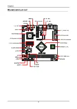
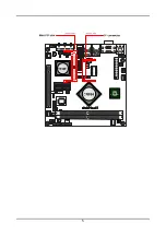
Page 12: ...Chapter 1 4 MAINBOARD LAYOUT ...
Page 13: ...5 ...
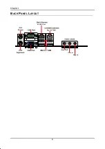
Page 14: ...Chapter 1 6 BACK PANEL LAYOUT ...
Page 35: ...27 CHAPTER 3 BIOS Setup This chapter gives a detailed explanation of the BIOS setup functions ...