


Installation
15
Case Connector: F_PANEL
The F_PANEL pin header allows you to connect the power switch, reset switch,
power LED, sleep LED, HDD LED and the case speaker.
Pin Signal
Pin Signal
1
+5VDUAL
2
+5V
3
+5VDUAL
4
HD_LED
5
-PLED
6
PW_BN
7
+5V
8
GND
9
NC
10
RST_SW
11
NC
12
GND
13
SPEAK
14
+5V
15
Key
16
-SLEEP_LED
Power LED (-PLED)
The LED will light when the system is on. If the system is in S1 (POS - Power
On Suspend) or S3 (STR - Suspend To RAM) state, the LED will blink.
HDD LED (HD_LED)
HDD LED shows the activity of a hard disk drive. Avoid turning the power off when
the HDD LED is still on. Connect the HDD LED from the system case to this pin.
Power Switch (PW_BN)
Connect to a 2-pin power button switch. Pressing this button will turn the
system power on or off.
Speaker (SPEAK)
The speaker from the system case is connected to this pin.
Reset Switch (RST_SW)
The reset switch is used to reboot the system rather than turning the power
ON/OFF. Avoid rebooting the system, if the HDD is still working. Connect
the reset switch from the system case to this pin.
Sleep LED (SLEEP_LED)
The SLEEP LED is lit when the system is in the S1 (POW-Power On Suspend)
Summary of Contents for EPIA-SN
Page 1: ...User s Manual EPIA SN Version 1 22 September 25 2008 ...
Page 8: ...iv This page is intentionally left blank ...
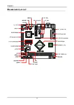
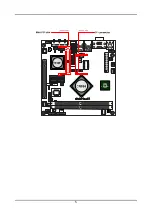
Page 12: ...Chapter 1 4 MAINBOARD LAYOUT ...
Page 13: ...5 ...
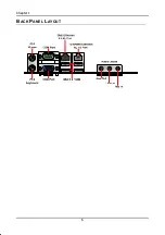
Page 14: ...Chapter 1 6 BACK PANEL LAYOUT ...
Page 35: ...27 CHAPTER 3 BIOS Setup This chapter gives a detailed explanation of the BIOS setup functions ...